标签:range pen real gif muti seve red nali comm
Activity 5.2.5:
Configuring STPNOTE TO USER: Although you can complete this activity without printed instructions, a PDF version is available on the text side of the same page from which you launched this activity.
Learning Objectives
- Examine the STP default state
- Configure the root bridge
- Configure the backup root bridge
- Finalize STP configuration
Introduction
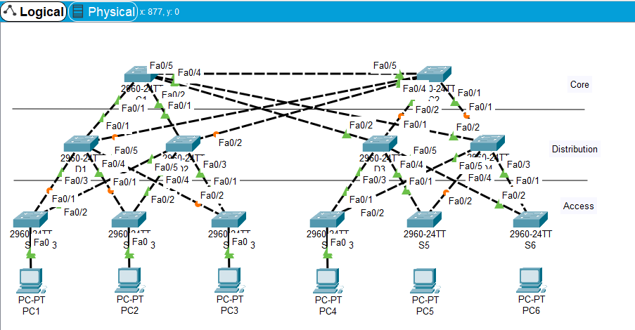
In this activity, the switches are "out of the box" without any configuration. You will manipulate the root bridge election so that the core switches are chosen before the distribution or access layer switches.
Task 1: Examine the STP Default State
Step 1. Examine link lights.
When STP is fully converged, the following conditions exist:
- All PCs have green link lights on the switched ports.
- Access layer switches have one forwarding uplink (green) to a distribution layer switch and a blocking uplink (amber) to a core layer switch.
- Distribution layer switches have one forwarding uplink (green) to a core layer switch and a blocking uplink (amber) to another core layer switch.
Step 2. Switch to Simulation mode.
Step 3. Determine the root bridge.
Click Capture/Forward. Without looking at BPDU detail, MAC addresses, or the show spanning-tree command, can you tell which switch is the root bridge?
Can you think of a reason why this switch is not a good choice as root?
Task 2: Configure the Root Bridge
Step 1. Configure the root bridge.
One of the core switches should be root, and the other should be the backup root. Switch to Realtime mode and configure C1 with a priority of 4096.
Step 2. Switch between Realtime and Simulation modes.
Switch between Realtime mode and Simulation mode several times until all ports on C1 are green.
Step 3. Switch to Simulation mode.
Step 4. Make sure C1 is the root bridge.
Click Capture/Forward several times to watch configuration BPDUs. C1 should be initiating the propagation of BPDUs.
Step 5. Check results.
Your completion percentage should be 17%. If not, click Check Results to see which required components are not yet completed.
Task 3: Configure the Backup Root Bridge
Step 1. Configure the backup root bridge.
The other core switch serves as a backup root bridge. Switch to Realtime mode and configure C2 with a priority of 8192.
Step 2. Switch between Realtime and Simulation modes.
Switch between Realtime mode and Simulation mode several times until all ports on C2 are green.
Step 3. Examine links attached to C2.
What is unique about the C2 links to the distribution layer switches that you do not see with C1 links?
Step 4. Check results.
Your completion percentage should be 33%. If not, click Check Results to see which required components are not yet completed.
Task 4: Finalize STP Configuration
Best practice is to never have an access layer switch become root. You could ensure this by configuring all access layer switches with a priority higher than the default. However, because there are fewer distribution switches, it is more efficient to configure these switches with a slightly higher priority than the backup root switch.
Step 1. Configure distribution switches.
Configure D1, D2, D3, and D4 with a priority of 12288.
Step 2. Check results.
Your completion percentage should be 100%. If not, click Check Results to see which required components are not yet completed.
All contents are Copyright ? 1992?007 Cisco Systems, Inc. All rights reserved. This document is Cisco Public Information.
The topology is shown below:
Specific operation command:

 1 C1:
 2 Switch>en
 3 Switch#conf t
 4 Switch(config)#spanning-tree mode pvst
 5 Switch(config)#spanning-tree vlan 1 priority 4096
 6 C2:
 7 Switch>en
 8 Switch#conf t
 9 Switch(config)#spanning-tree mode pvst
10 Switch(config)#spanning-tree vlan 1 priority 8192
11 D1、D2、D3、D4:
12 Switch>en
13 Switch#conf t
14 Switch(config)#spanning-tree mode pvst
15 Switch(config)#spanning-tree vlan 1 priority 12288
1. Complete the device configuration according to the instructions given above
2. Test the communication of various VLANs by Ping command, including the communication within and between VLANs
3. Observe the forwarding process of ping packet
4. The experiment is completed in PT software, which needs to be realized by PVST+. The example command in the courseware is MSTP configuration command, which is for reference only.
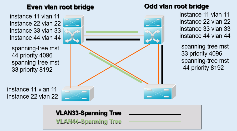
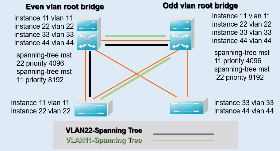
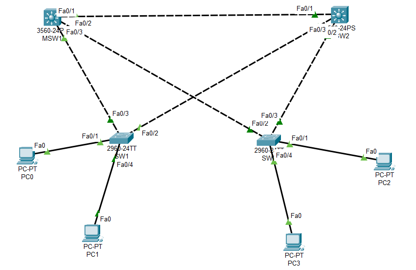
The topology and concrete requirements are shown below:
Specific operation command:
  1 =====Switch0:=====
  2 Switch>en
  3 Switch#conf t
  4
  5 Switch(config)#vlan 11
  6 Switch(config-vlan)#name vlan11
  7 Switch(config-vlan)#vlan 22
  8 Switch(config-vlan)#name vlan22
  9 Switch(config-vlan)#ex
 10
 11 Switch(config)#int fa0/1
 12 Switch(config-if)#swi mode ac
 13 Switch(config-if)#swi ac vlan 11
 14 Switch(config-if)#no shut
 15 Switch(config-if)#ex
 16 Switch(config)#int fa0/4
 17 Switch(config-if)#swi mode ac
 18 Switch(config-if)#swi ac vlan 22
 19 Switch(config-if)#no shut
 20 Switch(config-if)#ex
 21
 22 Switch(config)#int range fa0/2, fa0/3
 23 Switch(config-if-range)#swi mode trunk
 24 Switch(config-if-range)#no shut
 25 Switch(config-if-range)#ex
 26
 27
 28 =====Switch1:=====
 29 Switch>en
 30 Switch#conf t
 31
 32 Switch(config)#vlan 33
 33 Switch(config-vlan)#name vlan33
 34 Switch(config-vlan)#vlan 44
 35 Switch(config-vlan)#name vlan44
 36 Switch(config-vlan)#ex
 37
 38 Switch(config)#int fa0/1
 39 Switch(config-if)#swi mode ac
 40 Switch(config-if)#swi ac vlan 33
 41 Switch(config-if)#no shut
 42 Switch(config-if)#ex
 43 Switch(config)#int fa0/4
 44 Switch(config-if)#swi mode ac
 45 Switch(config-if)#swi ac vlan 44
 46 Switch(config-if)#no shut
 47 Switch(config-if)#ex
 48
 49 Switch(config)#int range fa0/2, fa0/3
 50 Switch(config-if-range)#swi mode trunk
 51 Switch(config-if-range)#no shut
 52 Switch(config-if-range)#ex
 53
 54
 55
 56 =====Mutilayer Switch0:=====
 57 Switch>en
 58 Switch#conf t
 59
 60 Switch(config)#vlan 11
 61 Switch(config-vlan)#vlan 22
 62 Switch(config-vlan)#vlan 33
 63 Switch(config-vlan)#vlan 44
 64 Switch(config-vlan)#ex
 65
 66 Switch(config)#int range fa0/1-3
 67 Switch(config-if-range)#swi trunk encapsulation dot1q
 68 Switch(config-if-range)#swi mode trunk
 69 Switch(config-if-range)#no shut
 70 Switch(config-if-range)#ex
 71
 72 Switch(config)#int vlan 22
 73 Switch(config-if)#ip add 192.168.22.1 255.255.255.0
 74 Switch(config-if)#no shut
 75 Switch(config-if)#ex
 76 Switch(config)#int vlan 44
 77 Switch(config-if)#ip add 192.168.44.1 255.255.255.0
 78 Switch(config-if)#no shut
 79 Switch(config-if)#ex
 80 Switch(config)#int vlan 11
 81 Switch(config-if)#ip add 192.168.11.1 255.255.255.0
 82 Switch(config-if)#no shut
 83 Switch(config-if)#ex
 84 Switch(config)#int vlan 33
 85 Switch(config-if)#ip add 192.168.33.1 255.255.255.0
 86 Switch(config-if)#no shut
 87 Switch(config-if)#ex
 88
 89 Switch(config)#spanning-tree mode pvst
 90 Switch(config)#spanning-tree vlan 22 root primary
 91 Switch(config)#spanning-tree vlan 44 root primary
 92 Switch(config)#spanning-tree vlan 11 root secondary
 93 Switch(config)#spanning-tree vlan 33 root secondary
 94 Switch(config)#spanning-tree vlan 22 priority 4096
 95 Switch(config)#spanning-tree vlan 11 priority 8192
 96 Switch(config)#spanning-tree vlan 33 priority 8192
 97 Switch(config)#spanning-tree vlan 44 priority 4096
 98 Switch(config)#ex
 99
100 Switch(config)#ip routing
101
102 =====Mutilayer Switch1:=====
103 Switch>en
104 Switch#conf t
105
106 Switch(config)#vlan 11
107 Switch(config-vlan)#vlan 22
108 Switch(config-vlan)#vlan 33
109 Switch(config-vlan)#vlan 44
110 Switch(config-vlan)#ex
111
112 Switch(config)#int range fa0/1-3
113 Switch(config-if-range)#swi trunk encapsulation dot1q
114 Switch(config-if-range)#swi mode trunk
115 Switch(config-if-range)#no shut
116 Switch(config-if-range)#ex
117
118 Switch(config)#int vlan 11
119 Switch(config-if)#ip add 192.168.11.1 255.255.255.0
120 Switch(config-if)#no shut
121 Switch(config-if)#ex
122 Switch(config)#int vlan 33
123 Switch(config-if)#ip add 192.168.33.1 255.255.255.0
124 Switch(config-if)#no shut
125 Switch(config-if)#ex
126 Switch(config)#int vlan 22
127 Switch(config-if)#ip add 192.168.22.1 255.255.255.0
128 Switch(config-if)#no shut
129 Switch(config-if)#ex
130 Switch(config)#int vlan 44
131 Switch(config-if)#ip add 192.168.44.1 255.255.255.0
132 Switch(config-if)#no shut
133 Switch(config-if)#ex
134
135 Switch(config)#spanning-tree mode pvst
136 Switch(config)#spanning-tree vlan 11 root primary
137 Switch(config)#spanning-tree vlan 33 root primary
138 Switch(config)#spanning-tree vlan 22 root secondary
139 Switch(config)#spanning-tree vlan 44 root secondary
140 Switch(config)#spanning-tree vlan 22 priority 8192
141 Switch(config)#spanning-tree vlan 11 priority 4096
142 Switch(config)#spanning-tree vlan 33 priority 4096
143 Switch(config)#spanning-tree vlan 44 priority 8192
144 Switch(config)#ex
Test PC configuration instances:
1 PC0: (VLAN 1)
2 IP: 192.168.11.11  subnet mask: 255.255.255.0     default gateway: 192.168.11.1
3 PC1:(VLAN 2)
4 IP: 192.168.22.22  subnet mask: 255.255.255.0     default gateway: 192.168.22.1
5 PC2: (VLAN 3)
6 IP: 192.168.33.33  subnet mask: 255.255.255.0     default gateway: 192.168.33.1
7 PC3:(VLAN 4)
8 IP: 192.168.44.44  subnet mask: 255.255.255.0     default gateway: 192.168.44.1
Cisco Packet Tracer :PVST Self-detection Experiment
标签:range pen real gif muti seve red nali comm
原文地址:https://www.cnblogs.com/elegantcloud/p/14923871.html
