标签:des style blog http color os strong io
Apparatus for making legacy network elements transparent to IEEE 1588 Precision Time Protocol operation. Network elements are wrapped by device(s) capable of providing either transparent clock or boundary clock operation. In one embodiment, smart interface converters are used to provide transparent clock or boundary clock operation. The smart interface converters work cooperatively.
Embodiments in accordance with the present invention relate to time synchronization in computer networks, and more particularly, to IEEE 1588 time synchronization across network switches, hubs, and routers.
Achieving time synchronization in computer networking is still a challenging task. Different elements of the network, such as PCs, workstations, servers, and devices such as routers and switches, and even VoIP phones today use NTP (Network Time Protocol) to get and set their epoch (time) from network-based NTP servers. NTP provides time accuracy on the order of tens of milliseconds. In most cases, this is sufficient.
In areas such as test and process automation, requirements are more strict, requiring time synchronization between networked devices on the order of sub-microsecond accuracy.
This may be accomplished by using GPS-based solutions. However, even if the cost of GPS-based equipment at each node is acceptable, delivery of GPS signals to each location is often not practical, due to the cost of cabling, or due to the requirement of an antenna with a clear view of the necessary number of GPS satellites. When used, though, GPS can provide time synchronization on the order of 50 nanoseconds.
In test and measurement applications, such as measuring one-way packet delays in networks, accuracy on the order of sub-milliseconds is required. Deploying GPS at various points in a network to perform the required network measurements is economically and practically feasible. When it could be envisioned that a region of a computer network might have a few GPS receivers, it would not be practical to equip all network elements with direct access to GPS accuracy.
In recent years the process automation industry has started deploying the IEEE 1588 standard (IEEE 1588-2002, incorporated herein by reference and referred to as 1588) to perform time synchronization between various devices. Unfortunately, in its current form 1588 is limited to very small networks, typically a LAN segment. IEEE 1588 makes the assumption that delays introduced by network elements are symmetrical and uniform. In order for IEEE 1588 to be deployed across wide area networks (WANs), significant investment is required in IEEE 1588 compliant network elements such as switches, hubs, routers, and the like.
There are two methods known in IEEE 1588 to deal with varying and asymmetrical delays at the network switching and routing elements. These delays occur naturally due to the nature of packet-switched traffic. As packets arrive at ports of a network element such as a router or switch, they must be identified and queued to the proper destination. This process introduces variable delays, particularly if multiple packets are queued for the same destination. One method of reducing these delays is to use a boundary clock, and another is to use a transparent clock.
In examining the boundary clock solution, first consider an IEEE 1588 master clock in device A directly connected to an IEEE 1588 slave clock in device B. IEEE 1588 precision time protocol (PTP) messages pass between A and B, establishing and maintaining B‘s clock in synchrony with A. Introducing a network element such as a router or switch between A and B introduces additional, varying delays in the propagation of IEEE 1588 messages. With a boundary clock, the network element (usually a switch or a router) runs the IEEE 1588 PTP protocol, and is synchronized to an attached master clock, as an example, device A. The boundary clock in turn acts as a master clock to all attached slaves, as an example, device B. Boundary clocks do not pass IEEE 1588 PTP messages.
The boundary clock solution requires the network element at the MAC/PHY level to redirect IEEE 1588 signals to the built-in boundary clock. If multiple network elements are present in the path between devices A and B, all these network elements must provide boundary clock capabilities.
A transparent clock passes IEEE 1588 messages, but either intercepts and modifies some of these messages to account for delays introduced by the network element, or sends follow-up messages containing IEEE 1588 packet delay information. One implementation of a transparent switch calculates how much time a SYNC packet spends in the network element, and then modifies the timestamp of the associated FOLLOW UP packet to account for this delay; similarly, the switch calculates how much time the DELAY REQ packet spends in the network, and modifies the timestamp of the associated DELAY RES packet. The transparent clock functionality must be built into the network element.
Such solutions become more complex when multiple network elements may intervene between an IEEE 1588 master clock and IEEE 1588 slave clocks.
Delays to IEEE 1588 time protocol packets caused by network elements are compensated for by an external device that wraps the legacy network elements with cooperating smart interface converters.
In a first embodiment, a transparent clock is provided. The smart interface converters timestamp certain IEEE 1588 packets, and either modify the timestamps in IEEE 1588 packets, or send calculated delays as part of IEEE 1588 packets. The smart interface converter connected to the IEEE 1588 master clock may support more than one smart interface converter slave. An out of band link may be used to synchronize smart interface converter clocks.
In a second embodiment, a boundary clock is formed by connecting smart interface converters to legacy network elements. One smart interface converter paired with an IEEE 1588 master clock acts as a IEEE 1588 slave. One or more additional smart interface converters act as IEEE 1588 master clocks supporting IEEE 1588 slave clocks. In some implementations, the 1588 slave smart interface converter sends synchronization pulses to the IEEE 1588 master smart interface converters using an out of band link, and periodically sends EPOCH packets to maintain synchronized clocks.
Network elements such as switches, routers, and the like introduce variable and unpredictable delays in packet traffic, including IEEE 1588 precision time protocol (PTP) traffic. The present invention provides network independent devices which wrap legacy network elements and provide IEEE 1588 network element delay transparency. This transparency may be provided in a distributed fashion by wrapping the network elements with cooperating smart interface converters (hereafter SIC).
Standard interface converters are pluggable building blocks used in many networking devices such as switches, hubs, routers, and the like, and are used to convert high speed signals from a first medium to a second medium. As an example, one popular type of standard interface converter known as a GBIC converts signals from optical to electrical form; optical signals carried on fiber optic cables being used to communicate over the network, and electrical signals being used within the device housing the GBIC. Other forms convert signals from twisted-pair copper conductors used in high-speed networks to electrical signals suitable for the network device.
A smart interface converter (SIC) is a standard interface converter with additional logic allowing it to process packets on the fly. This additional logic may include the ability to query the status of the SIC, perform internal tests, and/or perform data capture and analysis. The SIC device also adds the ability to inject data packets into the high speed data stream, and to modify the contents of data packets on the fly. Further details of SIC devices are described in detail in "A Method of Creating Low-Bandwidth Channel within a Packet Stream," application Ser. No. 10/688,340, filed Oct. 17, 2003, the entire disclosure of which is hereby incorporated by reference.
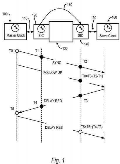
A first embodiment of the present invention is shown in?FIG. 1. This embodiment provides a distributed transparent clock which is wrapped around single or multiple network elements such as routers, switches, and the like. The network elements may be legacy equipment that are not IEEE 1588 aware. Distributed operation is performed by at least two cooperating SICs. Each cooperating SIC timestamps IEEE 1588 SYNC and DELAY REQ packets. The cooperating SICs modify FOLLOW UP and DELAY RESP packets on the fly by adjusting their timestamps.
IEEE 1588 master clock?100?communicates?110?to smart interface converter (SIC)?120. SIC?120?communicates with network elements?130, which may be one or more switches, routers, or the like. SIC?140?also communicates with network elements?130, and communicates?150?with IEEE 1588 slave clock?160. SIC?120, a designated master clock for out of band local clock synchronization with other SIC devices, also sends timing signals via out of band channel?170?to SIC?140. Communications paths?110?and?150?are preferably Ethernet links. Out of band channel?170?may be a coaxial cable, or other signaling medium such as a fiber optic link, free radiating optical link, or RF link. SIC?120?and SIC?140?pass packet traffic bidirectionally. While?FIG. 1?shows a single master SIC?120?and a single slave SIC?140, multiple slave SICs may be present.
Referring to the timing diagram in?FIG. 1, Master clock?100?sends SYNC packet at time T0. This packet passes through SIC120?where it is timestamped at time T1. The SYNC packet passes through SIC?120?and network element?130?to SIC?140. SIC?140?takes another timestamp at time T2. According to the IEEE 1588 PTP protocol Master clock?100?sends a FOLLOW UP packet containing original timestamp T0. Because packets such as SYNC could be delayed by an unpredictable time interval at network element?130, according to the present invention, the FOLLOW UP packet is modified on the fly when it passes through SIC?120, including the T1?timestamp in the FOLLOW UP packet. When the FOLLOW UP packet passes through SIC?140, the original T0?timestamp is modified by adjusting for the delay, i.e. T0=T0?(T2?T1) and inserted back into the FOLLOW UP packet on the fly, and passed to IEEE 1588 slave?160. Similar processing takes place with the DELAY REQ and DELAY RES packets.
In an alternative embodiment, rather than modifying FOLLOW UP and DELAY RES packets, packets containing the necessary timestamps and sequence ID information between the SICs. As an example, rather than have SIC?120?modify the FOLLOW UP packet with timestamp T1, SIC?120?could send a packet containing the proper sequence ID and the T1timestamp to SIC?140. Then Sic?140?could calculate network element delays for the SYNC/DELAY REQ packets, and pass this data to IEEE 1588 slave?160.
In order to provide accurate timestamping, SICs?120?and?140?synchronize their local clocks with each other via out of band channel?170. In one embodiment, a coaxial cable is used. An optical cable may be used, or free-radiating signals such as RF or optical signals may be used. If SIC?120?and?140?are co-located, for example in the same enclosure, channel?170?may be a simple electrical connection or a trace on a printed circuit board interconnecting the devices.
One of the SIC devices, SIC?120?in the example shown, is designated as a master for clock synchronization sends a periodic strobe pulse to synchronize the frequencies of other SIC device clocks. In addition, on a periodic basis such as once per second or some defined interval, a special strobe signal is sent out to indicate a time boundary condition. Upon receiving the special strobe signal, the slave SIC devices adjust their local clocks to the appropriate time boundary accordingly. As an example, in a given implementation SIC?120?sends out a strobe pulse every 1.6 microseconds. This periodic strobe allows other SIC devices to synchronize their clock frequencies. Once per second SIC?120?sends out a special strobe which instructs the other SIC devices to set the fractional seconds portion of their local clocks to zero. This process insures that SIC device clocks are synchronized both in terms of frequency and time.
While the out of band clock synchronization signal is shown in?FIG. 1?originating from SIC?120, this signal could be supplied by an external source, as an example, an external source using a high grade oscillator.
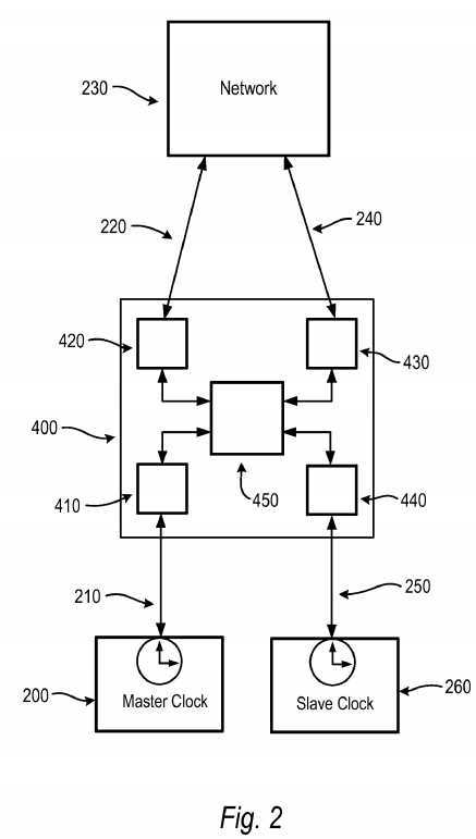
In an alternate embodiment, SIC?120?and SIC?140?may not only be co-located, but may share logic. In such an embodiment, for example where SIC?120?and?140?share the same clock generation circuitry, the use of an out of band channel to synchronize SIC clocks is not necessary. This would be the case, for example, if multiple SIC devices were implemented on one FPGA. Such an embodiment is shown in?FIG. 2. IEEE master clock?200?communicates?210?with device400. One channel of device?400, functionally similar to SIC?120?of?FIG. 1, comprises PHY?410, shared logic?450, and PHY420. PHY?420?communicates?220?with network elements?230. A second channel of device?400, functionally similar to SIC140?of?FIG. 1, comprises PHY?430, shared logic?450, and PHY?440. This channel communicates?240?with network elements230, and communicates?250?with IEEE 1588 slave clock?260.
An additional embodiment of the present invention is shown in?FIG. 3, providing a distributed boundary block. In this embodiment, each SIC device implements the IEEE 1588 PTP protocol, establishing separate PTP sessions.
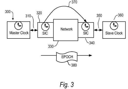
IEEE 1588 master clock?300?communicates?310?with SIC?320?which acts as an IEEE 1588 slave clock. SIC?330?acts as a IEEE 1588 master clock as it communicates?350?between network?330?and IEEE 1588 slave clock?360.
Using IEEE 1588 protocols, SIC?320?synchronizes its internal clock with that of IEEE master?300. SIC?340?acts as IEEE 1588 master clock, with IEEE 588 slave clock?360?synchronizing its clock to SIC?340.
SIC?320?synchronizes SIC?340‘s clock by sending periodic synch pulses via out of band link?370. SIC?320?also injects a special EPOCH packet into the datastream through network element?330?directed to SIC?340. SIC?340?uses this packet to synchronize its EPOCH. SIC?320?sends a special pulse via out of band link?370?to indicate to SIC?340?that the follow up EPOCH packet will have EPOCH data related to this event.
In an embodiment where SIC?320?and SIC?340?are co-located or share processing circuitry, such as shown in?FIG. 2, the use of the out of band channel and transmission of EPOCH packets may not be necessary.
SRC=https://www.google.com.hk/patents/US7689854
标签:des style blog http color os strong io
原文地址:http://www.cnblogs.com/coryxie/p/3890740.html