上一篇主要介绍了图像拼接的一些原理和方法,这一篇将主要介绍步骤和例程:
接上一篇:
基于特征的接拼方法,分为四个步骤
1、特征检测:从图像中检测出显著且独特的图像特征,诸如:闭合区域,直线段,边缘,轮廓,点等。
2、特征匹配:从相似度确定图像之间特征的对应关系,又分为如下几类:
2.1:使用空域关系的方法
2.2:使用不变描述符的方法
2.3:松弛方法
2.4:金字塔和小波方法
3、变换模型的估计:变换函数选择和函数参数估计
4、图像变换和重采样:可以通过前向或后向的方式来实现,插值的方法有最近邻插值、双线性插值、双三次函数插值、二次样条插值、三次B样条插值、高阶B样条插值。
基于特征的方法普遍适用于局部结构信息更显著的情况,能够处理图像之间复杂变形的情况,不足之处是特征检测困难且不稳定,最关键的一点是需要有一种判断力很强的、鲁棒性能好的且对图像之间变化保持不变的特征匹配算法。
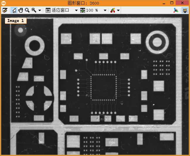
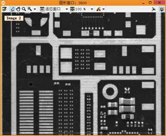
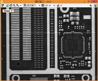
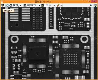
下面是Halcon自带例程,如何拼接图像
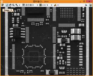
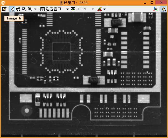
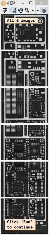
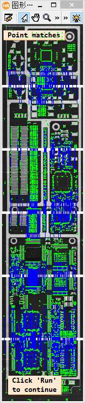
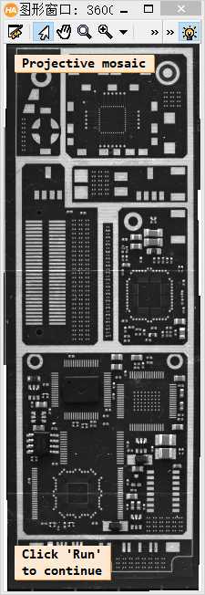
  1 **此例程讲解了如何将几张局部的PCB图像拼接居一张大的马赛克PCB图像。
  2 **此例程使用算子proj_match_points_ransac和算子 gen_projective_masaic完成上述工作。
  3 **请注意:这个PCB图像有一几处看起来像拼接逢合线的破损点,为了更好的区分真正的缝合线,例程呈现逢合线。
  4 dev_update_off ()
  5 dev_close_window ()
  6 dev_open_window (0, 0, 640, 480, ‘white‘, WindowHandle)
  7 dev_set_color (‘green‘)
  8 set_display_font (WindowHandle, 14, ‘mono‘, ‘true‘, ‘false‘)
  9 **一张一张的读取图像。
 10 gen_empty_obj (Images)
 11 for J := 1 to 6 by 1
 12     read_image (Image, ‘mosaic/pcb_‘ + J$‘02‘)
 13     concat_obj (Images, Image, Images)
 14     dev_display (Image)
 15     disp_message (WindowHandle, ‘Image ‘ + J$‘d‘, ‘image‘, -1, -1, ‘black‘, ‘true‘)
 16     wait_seconds (1)
 17 endfor
 18 disp_continue_message (WindowHandle, ‘black‘, ‘true‘)
 19 stop ()
 20 * To show the point matches that are used to compute the projective
 21 * transformation between the images, we will show all images in a large
 22 * tiled image with some space between the images so that the extents
 23 * of the images are easily visible.
 24 dev_set_window_extents (-1, -1, 640 / 4, 2980 / 4)
 25 tile_images_offset (Images, TiledImage, [0,500,1000,1500,2000,2500], [0,0,0,0,0,0], [-1,-1,-1,-1,-1,-1], [-1,-1,-1,-1,-1,-1], [-1,-1,-1,-1,-1,-1], [-1,-1,-1,-1,-1,-1], 640, 2980)
 26 dev_clear_window ()
 27 dev_display (TiledImage)
 28 disp_message (WindowHandle, ‘All 6 images‘, ‘window‘, 12, 12, ‘black‘, ‘true‘)
 29 disp_message (WindowHandle, ‘Click \‘Run\‘\nto continue‘, ‘window‘, 2980 / 4 - 50, 12, ‘black‘, ‘true‘)
 30 stop ()
 31 * Now we compute point matches between the five pairs of images and with this
 32 * the projective transformation between the image pairs.  Note that the code
 33 * below calls the point operator for each image pair.  Since the images form
 34 * a strip, with a little book keeping we could make the process a little more
 35 * efficient by saving the points from the last iteration (ImageT in pair J will
 36 * be identical to ImageF in pair J+1).  This is not done here because such an
 37 * optimization would be quite cumbersome in the general case where the images
 38 * can lie in a general configuration that cannot be represented by a strip.
 39 dev_clear_window ()
 40 dev_display (TiledImage)
 41 disp_message (WindowHandle, ‘Point matches‘, ‘window‘, 12, 3, ‘black‘, ‘true‘)
 42 * We define the image pairs, i.e., which image should be mapped to which image.
 43 From := [1,2,3,4,5]
 44 To := [2,3,4,5,6]
 45 Num := |From|
 46 * We need a variable to accumulate the projective transformation matrices.
 47 ProjMatrices := []
 48 * Furthermore, since we want to create a rigid mosaic below we need to
 49 * accumulate all the point correspondences and the number of matches per
 50 * image pair.
 51 Rows1 := []
 52 Cols1 := []
 53 Rows2 := []
 54 Cols2 := []
 55 NumMatches := []
 56 * Now we can determine the transformations between the five image pairs.
 57 for J := 0 to Num - 1 by 1
 58     F := From[J]
 59     T := To[J]
 60     select_obj (Images, ImageF, F)
 61     select_obj (Images, ImageT, T)
 62     * Extract the points in both images.
 63     points_foerstner (ImageF, 1, 2, 3, 200, 0.3, ‘gauss‘, ‘false‘, RowJunctionsF, ColJunctionsF, CoRRJunctionsF, CoRCJunctionsF, CoCCJunctionsF, RowAreaF, ColAreaF, CoRRAreaF, CoRCAreaF, CoCCAreaF)
 64     points_foerstner (ImageT, 1, 2, 3, 200, 0.3, ‘gauss‘, ‘false‘, RowJunctionsT, ColJunctionsT, CoRRJunctionsT, CoRCJunctionsT, CoCCJunctionsT, RowAreaT, ColAreaT, CoRRAreaT, CoRCAreaT, CoCCAreaT)
 65     * Determine the point matches and the transformation for the current
 66     * image pair.
 67     proj_match_points_ransac (ImageF, ImageT, RowJunctionsF, ColJunctionsF, RowJunctionsT, ColJunctionsT, ‘ncc‘, 21, 0, 0, 480, 640, 0, 0.5, ‘gold_standard‘, 1, 4364537, ProjMatrix, Points1, Points2)
 68     * Accumulate the transformation matrix.
 69     ProjMatrices := [ProjMatrices,ProjMatrix]
 70     * Accumulate the point matches and number of point matches.
 71     Rows1 := [Rows1,subset(RowJunctionsF,Points1)]
 72     Cols1 := [Cols1,subset(ColJunctionsF,Points1)]
 73     Rows2 := [Rows2,subset(RowJunctionsT,Points2)]
 74     Cols2 := [Cols2,subset(ColJunctionsT,Points2)]
 75     NumMatches := [NumMatches,|Points1|]
 76     * Generate crosses that represent the extracted points in the tiled image.
 77     * Note that we have to take the row offsets of the images in the tiled image
 78     * into account.
 79     gen_cross_contour_xld (PointsF, RowJunctionsF + (F - 1) * 500, ColJunctionsF, 6, rad(45))
 80     gen_cross_contour_xld (PointsT, RowJunctionsT + (T - 1) * 500, ColJunctionsT, 6, rad(45))
 81     * Generate a representation of the matched point pairs as lines.  We create
 82     * XLD contours from the lines so that we can zoom into the graphics window
 83     * to take a closer look at the matches.
 84     RowF := subset(RowJunctionsF,Points1) + (F - 1) * 500
 85     ColF := subset(ColJunctionsF,Points1)
 86     RowT := subset(RowJunctionsT,Points2) + (T - 1) * 500
 87     ColT := subset(ColJunctionsT,Points2)
 88     gen_empty_obj (Matches)
 89     for K := 0 to |RowF| - 1 by 1
 90         gen_contour_polygon_xld (Match, [RowF[K],RowT[K]], [ColF[K],ColT[K]])
 91         concat_obj (Matches, Match, Matches)
 92     endfor
 93     * Now display the extracted data.
 94     dev_set_color (‘blue‘)
 95     dev_display (Matches)
 96     dev_set_color (‘green‘)
 97     dev_display (PointsF)
 98     dev_display (PointsT)
 99 endfor
100 disp_message (WindowHandle, ‘Click \‘Run\‘\nto continue‘, ‘window‘, 2980 / 4 - 50, 12, ‘black‘, ‘true‘)
101 stop ()
102 * Finally, we can generate the mosaic image from the projective transformations.
103 gen_projective_mosaic (Images, MosaicImage, 2, From, To, ProjMatrices, ‘default‘, ‘false‘, MosaicMatrices2D)
104 get_image_size (MosaicImage, Width, Height)
105 dev_set_window_extents (-1, -1, Width / 3, Height / 3)
106 dev_clear_window ()
107 dev_display (MosaicImage)
108 disp_message (WindowHandle, ‘Projective mosaic‘, ‘window‘, 12, 12, ‘black‘, ‘true‘)
109 disp_message (WindowHandle, ‘Click \‘Run\‘\nto continue‘, ‘window‘, Height / 3 - 50, 12, ‘black‘, ‘true‘)
110 stop ()
111 * To show more clearly that the folds visible in the image do not result from the
112 * mosaicking, we display the seams between the images in the mosaic image.
113 * This can be done most easily by creating an image that contains the border
114 * of the images, generating a mosaic from it, and segmenting the resulting
115 * mosaic image.
116 get_image_size (Image, Width, Height)
117 gen_image_const (ImageBlank, ‘byte‘, Width, Height)
118 gen_rectangle1 (Rectangle, 0, 0, Height - 1, Width - 1)
119 paint_region (Rectangle, ImageBlank, ImageBorder, 255, ‘margin‘)
120 gen_empty_obj (ImagesBorder)
121 for J := 1 to 6 by 1
122     concat_obj (ImagesBorder, ImageBorder, ImagesBorder)
123 endfor
124 gen_projective_mosaic (ImagesBorder, MosaicImageBorder, 2, From, To, ProjMatrices, ‘default‘, ‘false‘, MosaicMatrices2D)
125 threshold (MosaicImageBorder, Seams, 128, 255)
126 dev_clear_window ()
127 dev_display (MosaicImage)
128 disp_message (WindowHandle, ‘Seams between the\nimages‘, ‘window‘, 12, 12, ‘black‘, ‘true‘)
129 dev_set_color (‘yellow‘)
130 dev_display (Seams)
131 disp_message (WindowHandle, ‘Click \‘Run\‘\nto continue‘, ‘window‘, 550, 12, ‘black‘, ‘true‘)
132 stop ()
133 * If you look very closely at the projective mosaic above, you may note that
134 * there is a very slight projective distortion in the mosaic.  This happens
135 * because the transformations cannot be determined with perfect accuracy
136 * because of very small errors in the point coordinates due to noise.  Because
137 * of the strip configuration, essentially the overlapping area between the image
138 * pairs can act like a hinge around which the images may rotate out of the image
139 * plane.  In this example, we know that the mapping between the images must
140 * be a rigid transformation.  If we want to force the transformation to be rigid
141 * we can simply use bundle_adjust_mosaic.
142 bundle_adjust_mosaic (6, 1, From, To, ProjMatrices, Rows1, Cols1, Rows2, Cols2, NumMatches, ‘rigid‘, MosaicMatrices2D, Rows, Cols, Error)
143 * Now, we can generate the mosaic image from the rigid transformations.
144 gen_bundle_adjusted_mosaic (Images, MosaicImageRigid, MosaicMatrices2D, ‘default‘, ‘false‘, TransMatrix2D)
145 get_image_size (MosaicImageRigid, Width, Height)
146 dev_set_window_extents (-1, -1, Width / 3, Height / 3)
147 dev_clear_window ()
148 dev_display (MosaicImageRigid)
149 disp_message (WindowHandle, ‘Rigid mosaic‘, ‘window‘, 12, 12, ‘black‘, ‘true‘)
带逢合线的图像 找定位点
最终图像:
下面我们看一下另一个例程:
这个例程使用proj_match_points_ransac_guided 和 gen_projective_mosaic
主要介绍如何使用金字塔算法快速获取两个图像的特征点进行拼接。
  1 * This example program shows how images can be combined
  2 * into a mosaic image using proj_match_points_ransac_guided
  3 * and gen_projective_mosaic.
  4 * It is shown how the calculation of the projection between two
  5 * images can be accelerated using an image pyramid.
  6 *
  7 * Initializations
  8 ImgPath := ‘3d_machine_vision/mosaic/‘
  9 ImgName := ‘bga_r_‘
 10 Times := []
 11 Colors := [‘red‘,‘coral‘,‘yellow‘,‘lime green‘]
 12 read_image (Images, ImgPath + ImgName + [‘01‘,‘06‘])
 13 dev_update_off ()
 14 dev_close_window ()
 15 dev_open_window_fit_size (0, 0, 640, 980, 320, 490, WindowHandle)
 16 dev_open_window_fit_size (0, 330, 490, 490, 1000, 490, WindowHandle1)
 17 set_display_font (WindowHandle, 14, ‘mono‘, ‘true‘, ‘false‘)
 18 set_display_font (WindowHandle1, 14, ‘mono‘, ‘true‘, ‘false‘)
 19 * The internal camera parameters of the used camera
 20 * (necessary to eliminate radial distortions)
 21 CamParam := [0.0121693,-2675.63,7.40046e-006,7.4e-006,290.491,258.887,640,480]
 22 change_radial_distortion_cam_par (‘adaptive‘, CamParam, 0, CamParOut)
 23 change_radial_distortion_image (Images, Images, Images, CamParam, CamParOut)
 24 * To show the point matches that are used to compute the
 25 * transformation between the images, we will show both images in a
 26 * tiled image with some space between the images so that the extents
 27 * of the images are easily visible.
 28 tile_images_offset (Images, TiledImage, [0,500], [0,0], [-1,-1], [-1,-1], [-1,-1], [-1,-1], 640, 980)
 29 *
 30 * Now we can determine the transformations between the image pairs.
 31 From := 1
 32 To := 2
 33 select_obj (Images, ImageF, From)
 34 select_obj (Images, ImageT, To)
 35 *
 36 * Repeat the calculation 4 times with a different number of pyramid levels
 37 for NumLevels := 1 to 4 by 1
 38     *
 39     dev_clear_window ()
 40     dev_set_window (WindowHandle)
 41     dev_clear_window ()
 42     dev_display (TiledImage)
 43     disp_message (WindowHandle, [‘Calculate point matches‘,‘with ‘ + NumLevels + ‘ pyramid levels‘,‘Please wait ...‘], ‘window‘, 20, 10, ‘black‘, ‘true‘)
 44     *
 45     * Calculate the projection between the two images
 46     * Check the procedure‘s comments for details
 47     count_seconds (S1)
 48     proj_match_points_ransac_pyramid (ImageF, ImageT, NumLevels, RowFAll, ColFAll, RowTAll, ColTAll, ProjMatrix, Points1, Points2)
 49     count_seconds (S2)
 50     Times := [Times,S2 - S1]
 51     *
 52     * Display point correspondences
 53     gen_cross_contour_xld (PointsF, RowFAll, ColFAll, 6, rad(45))
 54     gen_cross_contour_xld (PointsT, RowTAll + 500, ColTAll, 6, rad(45))
 55     RowF := subset(RowFAll,Points1)
 56     ColF := subset(ColFAll,Points1)
 57     RowT := subset(RowTAll,Points2) + 500
 58     ColT := subset(ColTAll,Points2)
 59     gen_empty_obj (Matches)
 60     for K := 0 to |RowF| - 1 by 1
 61         gen_contour_polygon_xld (Match, [RowF[K],RowT[K]], [ColF[K],ColT[K]])
 62         concat_obj (Matches, Match, Matches)
 63     endfor
 64     dev_display (TiledImage)
 65     dev_set_color (‘blue‘)
 66     dev_display (Matches)
 67     dev_set_color (‘green‘)
 68     dev_display (PointsF)
 69     dev_display (PointsT)
 70     disp_message (WindowHandle, [|RowF| + ‘ point matches‘,‘Time used: ‘ + (S2 - S1)$‘.3‘ + ‘ s‘], ‘window‘, 20, 10, ‘black‘, ‘true‘)
 71     *
 72     * Generate the mosaic image
 73     gen_projective_mosaic (Images, MosaicImage, 1, From, To, ProjMatrix, [2,1], ‘false‘, MosaicMatrices2D)
 74     *
 75     * Display mosaic image
 76     get_image_size (MosaicImage, Width, Height)
 77     dev_set_window (WindowHandle1)
 78     dev_resize_window_fit_image (MosaicImage, 0, 330, [400,700], 700)
 79     dev_clear_window ()
 80     dev_display (MosaicImage)
 81     disp_message (WindowHandle1, ‘Projective mosaic (used ‘ + NumLevels + ‘ pyramid levels)‘, ‘window‘, 20, 10, ‘black‘, ‘true‘)
 82     disp_continue_message (WindowHandle1, ‘black‘, ‘true‘)
 83     stop ()
 84 endfor
 85 *
 86 * Display execution times
 87 dev_set_window (WindowHandle)
 88 dev_close_window ()
 89 MaxTime := max(Times)
 90 BaseRow := 380
 91 RectHeight := 300
 92 disp_message (WindowHandle1, [‘Time in s:‘,‘(#levels used)‘], ‘image‘, BaseRow + 20, 10, ‘black‘, ‘true‘)
 93 for Index := 0 to |Times| - 1 by 1
 94     gen_rectangle1 (Rectangle, BaseRow - RectHeight * Times[Index] / MaxTime, 200 + Index * 100, BaseRow, 280 + Index * 100)
 95     disp_message (WindowHandle1, [Times[Index]$‘.3‘,‘(‘ + (Index + 1) + ‘)‘], ‘image‘, BaseRow + 20, 200 + 100 * Index, ‘black‘, ‘true‘)
 96     dev_set_color (Colors[Index])
 97     dev_set_draw (‘fill‘)
 98     dev_display (Rectangle)
 99 endfor
100 disp_finished_message (WindowHandle1, ‘black‘, ‘true‘)