标签:des style blog http color io os ar strong
An approach is provided in a hypervised computer system where a page table request is at an operating system running in the hypervised computer system. The operating system determines whether the page table request requires the hypervisor to process. If the determination reveals that the page table request requires the hypervisor, then the hypervisor is used to handle the request. However, if the determination reveals that the page table request does not require the hypervisor, then an indicator included in a page table entry corresponding to the request is read to determine if the page table entry is controlled by the operating system or the hypervisor. The operating system is able to update the page table entry if the indicator identifies the page table entry as being operating system controlled.
The present invention allows an operating system to manage address data structures rather than a hypervisor.
Traditionally in hypervised systems, an operating system manages storage (e.g. maintains the page table, etc.) using service calls to the hypervisor. In environments which set up and tear down huge numbers of short-lived applications (e.g. some types of web serving applications, etc.), the overhead of hypervisor intervention is costly in terms of performance. One approach used by some architectures (e.g. IA32, etc.) has been to create a second level of translation so that the operating system can maintain the first level of page translation, while the hypervisor continues to maintain the actual mapping to real address space. This approach can be costly both in terms of hardware lookaside resources and storage footprint for the tables (and resulting cache pressure). Traditionally, the hypervisor prevents the OS from accessing page tables using conventional storage protection mechanisms that are part of most memory management architectures.
An approach is provided in a hypervised computer system where a page table request is at an operating system running in the hypervised computer system. The operating system determines whether the page table request requires the hypervisor to process. If the determination reveals that the page table request requires the hypervisor, then the hypervisor is used to handle the request. However, if the determination reveals that the page table request does not require the hypervisor, then an indicator included in a page table entry corresponding to the request is read to determine if the page table entry is controlled by the operating system or the hypervisor. The operating system is able to update the page table entry if the indicator identifies the page table entry as being operating system controlled, otherwise the update is handled by the hypervisor.
The foregoing is a summary and thus contains, by necessity, simplifications, generalizations, and omissions of detail; consequently, those skilled in the art will appreciate that the summary is illustrative only and is not intended to be in any way limiting. Other aspects, inventive features, and advantages of the present invention, as defined solely by the claims, will become apparent in the non-limiting detailed description set forth below.
The present invention may be better understood, and its numerous objects, features, and advantages made apparent to those skilled in the art by referencing the accompanying drawings, wherein:
FIG. 1?is a block diagram of a data processing system in which the methods described herein can be implemented;
FIG. 2?is a network diagram of various types of data processing systems connected via a computer network;
FIG. 3?is a block diagram depicting the hypervisor and operating systems interaction with CPU components in order to manipulate memory management storage;
FIG. 4?is a first flowchart depicting steps taken by an operating system to handle an incoming page table request; and
FIG. 5?is a second flowchart depicting actions taken by the operating system to update the page table entry.
The following detailed description will generally follow the summary of the invention, as set forth above, further explaining and expanding the definitions of the various aspects and embodiments of the invention as necessary. To this end, this detailed description first sets forth a computing environment in?FIG. 1?that is suitable to implement the software and/or hardware techniques associated with the invention.
FIG. 1?illustrates information handling system?100, which is a simplified example of a computer system capable of performing the computing operations described herein. Information handling system?100?includes one or more processors?110coupled to processor interface bus?112. Processor interface bus?112?connects processors?110?to Northbridge?115, which is also known as the Memory Controller Hub (MCH). Northbridge?115?connects to system memory?120?and provides a means for processor(s)?110?to access the system memory. Graphics controller?125?also connects to Northbridge?115. In one embodiment, PCI Express bus?118?connects Northbridge?115?to graphics controller?125. Graphics controller?125?connects to display device?130, such as a computer monitor.
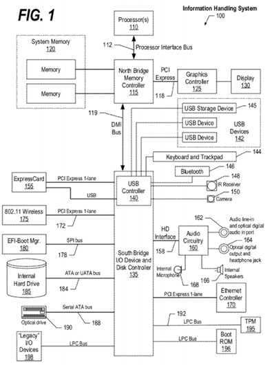
Northbridge?115?and Southbridge?135?connect to each other using bus?119. In one embodiment, the bus is a Direct Media Interface (DMI) bus that transfers data at high speeds in each direction between Northbridge?115?and Southbridge?135. In another embodiment, a Peripheral Component Interconnect (PCI) bus connects the Northbridge and the Southbridge. Southbridge?135, also known as the I/O Controller Hub (ICH) is a chip that generally implements capabilities that operate at slower speeds than the capabilities provided by the Northbridge. Southbridge?135?typically provides various busses used to connect various components. These busses include, for example, PCI and PCI Express busses, an ISA bus, a System Management Bus (SMBus or SMB), and/or a Low Pin Count (LPC) bus. The LPC bus often connects low-bandwidth devices, such as boot ROM?196?and "legacy" I/O devices (using a "super I/O" chip). The "legacy" I/O devices (198) can include, for example, serial and parallel ports, keyboard, mouse, and/or a floppy disk controller. The LPC bus also connects Southbridge?135?to Trusted Platform Module (TPM)?195. Other components often included in Southbridge?135?include a Direct Memory Access (DMA) controller, a Programmable Interrupt Controller (PIC), and a storage device controller, which connects Southbridge?135?to nonvolatile storage device?185, such as a hard disk drive, using bus?184.
ExpressCard?155?is a slot that connects hot-pluggable devices to the information handling system. ExpressCard?155supports both PCI Express and USB connectivity as it connects to Southbridge?135?using both the Universal Serial Bus (USB) the PCI Express bus. Southbridge?135?includes USB Controller?140?that provides USB connectivity to devices that connect to the USB. These devices include webcam (camera)?150, infrared (IR) receiver?148, keyboard and trackpad?144, and Bluetooth device?146, which provides for wireless personal area networks (PANs). USB Controller?140?also provides USB connectivity to other miscellaneous USB connected devices?142, such as a mouse, removable nonvolatile storage device?145, modems, network cards, ISDN connectors, fax, printers, USB hubs, and many other types of USB connected devices. While removable nonvolatile storage device?145?is shown as a USB-connected device, removable nonvolatile storage device?145?could be connected using a different interface, such as a Firewire interface, etcetera.
Wireless Local Area Network (LAN) device?175?connects to Southbridge?135?via the PCI or PCI Express bus?172. LAN device?175?typically implements one of the IEEE 802.11 standards of over-the-air modulation techniques that all use the same protocol to wireless communicate between information handling system?100?and another computer system or device. Optical storage device?190?connects to Southbridge?135?using Serial ATA (SATA) bus?188. Serial ATA adapters and devices communicate over a high-speed serial link. The Serial ATA bus also connects Southbridge?135?to other forms of storage devices, such as hard disk drives. Audio circuitry?160, such as a sound card, connects to Southbridge?135?via bus158. Audio circuitry?160?also provides functionality such as audio line-in and optical digital audio in port?162, optical digital output and headphone jack?164, internal speakers?166, and internal microphone?168. Ethernet controller?170?connects to Southbridge?135?using a bus, such as the PCI or PCI Express bus. Ethernet controller?170?connects information handling system?100?to a computer network, such as a Local Area Network (LAN), the Internet, and other public and private computer networks.
While?FIG. 1?shows one information handling system, an information handling system may take many forms. For example, an information handling system may take the form of a desktop, server, portable, laptop, notebook, or other form factor computer or data processing system. In addition, an information handling system may take other form factors such as a personal digital assistant (PDA), a gaming device, ATM machine, a portable telephone device, a communication device or other devices that include a processor and memory.
FIG. 2?is a network diagram of various types of data processing systems connected via a computer network.?FIG. 2provides an extension of the information handling system environment shown in?FIG. 1?to illustrate that the methods described herein can be performed on a wide variety of information handling systems that operate in a networked environment. Types of information handling systems range from small handheld devices, such as handheld computer/mobile telephone?210?to large mainframe systems, such as mainframe computer?270. Examples of handheld computer?210?include personal digital assistants (PDAs), personal entertainment devices, such as MP3 players, portable televisions, and compact disc players. Other examples of information handling systems include pen, or tablet, computer?220, laptop, or notebook, computer?230, workstation?240, personal computer system?250, and server?260. Other types of information handling systems that are not individually shown in?FIG. 2?are represented by information handling system?280. As shown, the various information handling systems can be networked together using computer network?200. Types of computer network that can be used to interconnect the various information handling systems include Local Area Networks (LANs), Wireless Local Area Networks (WLANs), the Internet, the Public Switched Telephone Network (PSTN), other wireless networks, and any other network topology that can be used to interconnect the information handling systems. Many of the information handling systems include nonvolatile data stores, such as hard drives and/or nonvolatile memory. Some of the information handling systems shown in?FIG. 2?depicts separate nonvolatile data stores (server?260?utilizes nonvolatile data store?265, mainframe computer?270?utilizes nonvolatile data store?275, and information handling system?280?utilizes nonvolatile data store?285). The nonvolatile data store can be a component that is external to the various information handling systems or can be internal to one of the information handling systems. In addition, removable nonvolatile storage device?145?can be shared among two or more information handling systems using various techniques, such as connecting the removable nonvolatile storage device?145?to a USB port or other connector of the information handling systems.
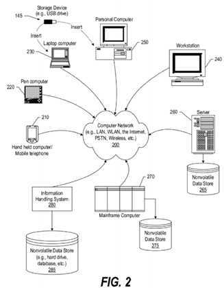
FIG. 3?is a block diagram depicting the hypervisor and operating systems interaction with CPU components in order to manipulate memory management storage. System memory?300?includes Memory Management Storage?310?that further include Page Table Entries (PTEs)?320?as well as eXtension Pointers (XPs). In storage constrained and highly dynamic computing environments, page table manipulations can be frequent enough that the hypervisor call (hcall) overhead causes performance degradation. This approach provides a technique and resources with which an operating system (370) can directly manipulate page table entries?320. In one embodiment, the page table structure includes of a hashed table. In one embodiment, the entry may be either a Page Table Entry (PTE) or an eXtension Pointer (XP), which points to a page containing 256 PTEs. The operating system may use a variety of data structures to track the allocation of storage, including the Page Table itself. Those structures which contain the real address reside in storage with a new storage attribute called Memory Management, which is used to protect the integrity of the Page Frame Descriptor (PFD). Each entry in Memory Management Storage (MMS)?310?is a quadword, with the Page Frame Descriptor, consisting of the real address, page size, and storage control bits?321?(WIMG) attribute information, located in fixed locations consistent with the Page Table Entry format.
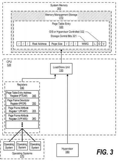
In one embodiment, MMS?310?is accessed freely by hypervisor?380?through Load/Store Unit?330?of CPU?325, and is accessed via registers?340?using defined instructions by operating system running on the system. Values stored in registers340?are processed by Load/Store Unit?330?to update PTE?320. In one embodiment, the Memory Management attribute is identified by control bits?321?(WIMG)=Ob1100. A second special?WIMG?combination (WIMG=Ob1101) is used to identify XPs in the hashed page table. In one embodiment where the second special?WIMG?combination is used, the kernel storage is mapped by page tables that are under the control of the hypervisor. It is also possible to have range registers or some such technique to create MMS?310?without the use of page tables. In some embodiments, hypervisor?380?might need to "steal" pages (e.g., for additional memory needs, etc.). In addition, in some embodiments, it might be necessary to differentiate PTEs that are under hypervisor control from those which may be manipulated by the operating system. Control indicator?322, also referred to as "the O bit" indicates whether the PTE can be managed by the OS (e.g., O=1) or may be updated only by the hypervisor (e.g., O=0). To ensure proper use of the page frames, the base address and the page size are provided and manipulated in a way that does not allow the operating system to access storage outside the bounds defined by the page frame real address and page size. In one embodiment, the operating system can alter the address and size to address a smaller page within the page provided by the hypervisor. In one embodiment, the operating system is further restricted in that it may not change the?WIMG?attributes.
Four registers?340?are used to communicate PTE data. The Page Frame Descriptor Register (PFDR)?350?is the repository for the authorized Page Frame Descriptor (i.e. the page frame base address, the page size, the?WIMG?attributes, and the valid bit). Note that in one embodiment, access to Page Frame Descriptor Register (PFDR)?350?is privileged and can be accessed by the operating system using the LPTE and STPTE instructions discussed above. In one embodiment, manipulation of the PFDR by the operating system is possible as a monolithic set of data using the LPTE and STPTE instructions. In this embodiment, the operating system is not permitted to manipulate individual fields of the PFDR. In addition, when the PTE is stored using STPTE, the PTE will be a consistent integration, or merger, of the PFDR content with PFAR1 and PFAR2, rather than solely a reflection of what is in the PFDR. In a further embodiment, for some system security implementations, it may be desirable to inhibit the operating system from reading the real address portion of the PFDR as this information may be considered secure. Page Frame Attribute Registers 1 and 2 (PFAR1?355, PFAR2?360) hold the other bits for a PTE. The Page Frame Attribute Registers also contain the bits that control page size, which may be programmed by the operating system, and identify a proper subset of the page specified in the PFDR. In this manner, in one embodiment, the operating system is able to make limited modifications to some of the fields that are included in the PFDR and one of either PFAR 1 or PFAR 2. For example, the operating system can change the L and LP values (the changed values go in PFAR1 and PFAR2, not PFDR) to specify a smaller page within the page it was originally given.
The Page Table Entry Address Register (PTEAR)?345?includes the effective address of the PTE to be updated and a valid bit that indicates the quadword is a PTE which the operating system may update. Page Table Entry Address Register (PTEAR)?345?is used to enforce the management state of a PTE when updating the PTE. In one embodiment, the PTEAR may only be loaded by using the LPTEAR instruction discussed below. The PTEAR includes the effective address of the PTE and a valid bit that indicates that the entry is a PTE (as opposed to an eXtension Pointer) and that the PTE is not in a hypervisor management state.
Four instructions are used to manage page table entries. These four instructions are hardware instructions executed by Load/Store Unit?330?of Central Processing Unit (CPU)?325. The instruction are as follows: First, Load Page Table Entry (LPTE) is an instruction that tests for the memory management attribute and that the PTE may be updated by the OS, and also the absence of the?WIMG?combination that indicates an eXtension Pointer as part of the load of the PFDR and PFARs (resetting the valid bit if the conditions are not met). Second, Store Page Table Entry (STPTE) is an instruction that stores the merge of the PFDR and the PFARs to a location in storage if the target quadword is not an eXtension Pointer and is not being managed by the hypervisor. As part of the merge operation, the STPTE instruction verifies that the L/LP bits supplied in the PFARs are consistent with those in the PFDR. As known by those skilled in the art, in one embodiment, the L/LP bits indicate the page size and, in some cases, the alignment of the page in storage. Third, Load Page Table Entry Address Register (LPTEAR) is an instruction that loads the effective address of the target PTE and checks to ensure that the quadword is not an eXtension Pointer and that the hypervisor is not managing the entry, setting a valid bit accordingly. Fourth, Page Frame Descriptor Invalidate (PFDI) is an instruction that sets the valid bit in the PFDR to zero.
To write a new PTE, the operating system first loads the address into the PTEAR using the LPTEAR instruction. The operating system then loads an authorized Page Frame Descriptor in the format of a PTE into the PFDR and PFARs (with L/LP bits replicated into the appropriate bits of the PFARs) using the LPTE instruction. The operating system then modifies the contents of the PFARs using the MFSPR and MTSPR instructions to establish the appropriate page size, protection attributes, and so forth. Last, the operating system uses the STPTE instruction to merge and store the PTE.
In one embodiment, Memory Management Storage?310?includes two types of memory-management related structures: Page Table Entries (PTE)?320?and eXtension Pointers (XPs). General access to Memory Management Storage using In one embodiment, Load and Store instructions are limited to hypervisor state (hypervisor?380). Non-hypervisor privileged software (e.g., operating systems?370) may access Memory Management Storage via the Load Page Table Effective Address Register (LPTEAR), Load Page Table Entry (LPTE), Load Real Address (LRA), Store eXtension Pointer, and Store Page Table Entry instructions. In one embodiment, other attempts to access Memory Management Storage?310?by non-hypervisor privileged software is considered a storage protection violation.
As outlined above, this approach provides an operating system operating in a hypervised system with some limited ability to load and store data to the memory management storage. Accessing memory management storage via the registers and the instructions described above allows the operating system to access memory management storage while maintaining the integrity of the page table through the processes performed by the instructions.
FIG. 4?is a first flowchart depicting steps taken by an operating system to handle an incoming page table request. Operating system processing is shown commencing at?400?whereupon, at step?410, a page table request is received. As shown, there can be many different request types including 1. reallocate page to another process, 2. change protection attributes, 3. subdivide page, 4. create another PTE to map to same real page, 5. manipulate reference and change bits, 6. change software control bits, 7. increase page size, 8. change storage control bits, 9. move page, and the like. Some of these pages may need the hypervisor to execute, while others may be performed by the operating system using registers340?introduced in?FIG. 3, and related text, above. Returning to?FIG. 4, a decision is made as to whether the page table request received at the operating system requires the hypervisor (decision?420). For example, in one embodiment, the hypervisor is required to increase a page size, to change the storage control bits, and to move a page. If the received request does not require the hypervisor, then decision?420?branches to the "no" branch whereupon, at step?425, a control indicator is checked (e.g., control indicator "O bit"?322?shown in?FIG. 3) in order to determine if the page table entry (e.g., PTE?320?shown in?FIG. 3) is hypervisor or operating system controlled. For example, in one embodiment, if the control indicator is "1" then the PTE is operating system controlled, and if the control indicator is "0" then the PTE is hypervisor controlled.
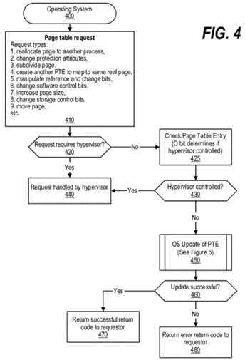
A decision is made as to whether the PTE is hypervisor controlled (decision?430). If the request is hypervisor controlled, then decision?430?branches to the "yes" branch. If either the request requires the hypervisor (decision?420?branching to the "yes" branch) or the control indicator identifies the hypervisor as controlling the PTE (decision?430?branching to the "yes" branch), then the hypervisor handles the request at step?440. On the other hand, if the request does not require the hypervisor (decision?420?branching to the "no" branch) and the PTE is not hypervisor controlled (decision?430?branching to the "no" branch), then the operating system updates the PTE at predefined process?450?(see?FIG. 5?and corresponding text for processing details). A decision is made as to whether the update performed by the operating system was successful (decision?460). If the update was successful, then decision?460?branches to the "yes" branch whereupon, at step?470, a successful return code is returned to the requestor indicating that the request was performed successfully. On the other hand, if the update attempted by the operating system was not successful, then decision?460?branches to the "no" branch whereupon, at step?480, an error is returned to the requestor indicating that the page table request was not successful.
FIG. 5?is a second flowchart depicting actions taken by the operating system to update the page table entry. This routine is called from predefined process?450?shown in?FIG. 4. Processing commences at?500?whereupon, at step?510, the operating system loads the address of the PTE into PTEAR register?345?using the LPTEAR instruction. The LPTEAR instruction validates that the PTE can be manipulated by the operating system and also loads the address of the PTE into the PTEAR register. At step?520, the PTE data is loaded from memory into various registers (PFDR?350, PFAR1?355, and PFAR2?360) using the LPTE instruction. The LPTE instruction uses the (now validated) address that was loaded in the PTEAR register during step?510?to load data to the various registers. At step?530, the operating system alters the data stored in PFAR1 and 2 (registers?355?and?360) to describe the new page that the operating system is mapping in system memory. After the various registers are loaded and the contents are altered as needed, at step?540, the operating system executes the Store Page Table Entry (STPTE) hardware instruction to store the new PTE into Memory Management Storage (MMS).
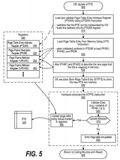
Block?550?shows steps performed by the Load/Store Unit of the CPU to execute the STPTE instruction. First, at step?560, the Load/Store Unit validates data stored in the registers, such as the contents stored in PFAR1 and 2 which could have been altered by the operating system during step?530. A decision is made by the Load/Store Unit, based on the validation of the data, as to whether the update to the PTE is allowed (decision?570). If the update is allowed, then decision?570branches to the "yes" branch whereupon, at step?580, the Load/Store Unit of the CPU updates PTE?320?using values loaded in registers?340. On the other hand, if the update is not allowed, then decision?570?branches to the "no" branch whereupon, at step?590, the Load/Store Unit causes an error to occur indicating that the PTE was not updated. After block550?concludes, at?595, processing returns to the calling routine (see?FIG. 4) with a result that indicates whether the update was allowed (performed).
SRC=https://www.google.com.hk/patents/US8645667
Operating system management of address-translation-related data structures and hardware lookasides
标签:des style blog http color io os ar strong
原文地址:http://www.cnblogs.com/coryxie/p/3989368.html