标签:mes led 参考 poi long this like OWIN tps
【Parallax Mapping】
Parallax mapping belongs to the family of displacement mapping techniques that displace or offset vertices based on geometrical information stored inside a texture.
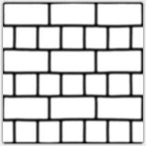
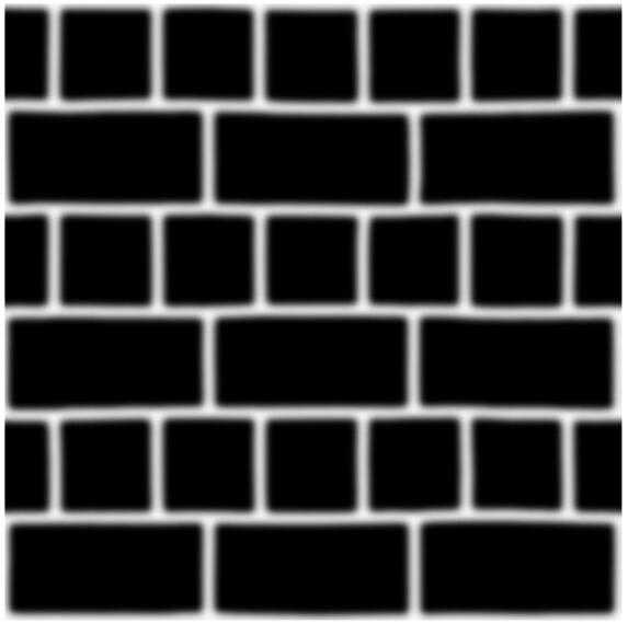
1、Height Map。
One way to do this is to take a plane with roughly 1000 vertices and displace each of these vertices based on a value in a texture that tells us the height of the plane at a specific area. Such a texture that contains height values per texel is called a height map. An example height map derived from the geometric properties of a simple brick surface looks a bit like this:
Taking a flat plane displaced with the above heightmap results in the following image:
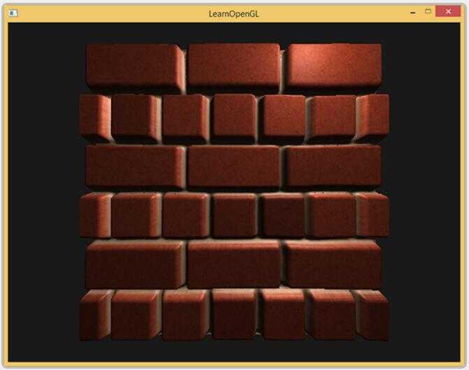
A problem with displacing vertices is that a plane needs to consist of a large amount of triangles to get a realistic displacement otherwise the displacement looks too blocky. As each flat surface could then require over 1000 vertices this quickly becomes computationally infeasible.
2、Parallax Mapping 理论。
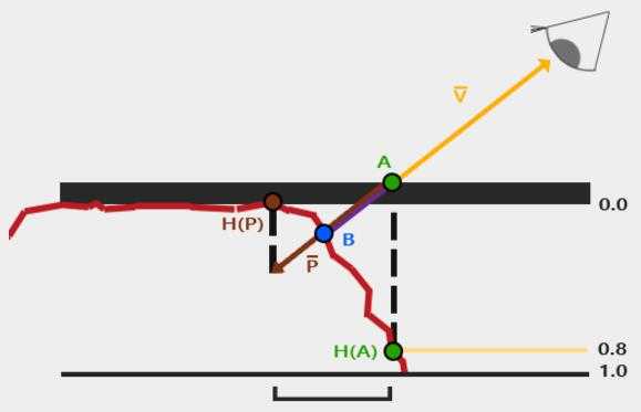
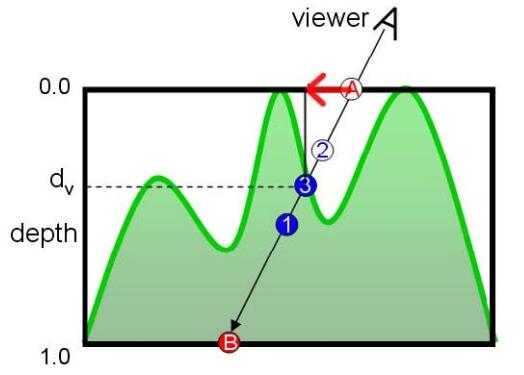
The idea behind parallax mapping is to alter the texture coordinates in such a way that it looks like a fragment‘s surface is higher or lower than it actually is, all based on the view direction and a heightmap.
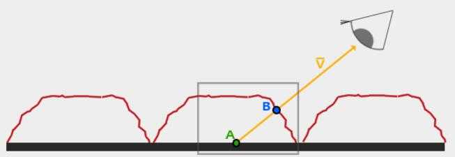
Red line represents the values in the heightmap. If the plane would have actual displacement the viewer would see the surface at point B.
Parallax mapping aims to offset the texture coordinates at fragment position A in such a way that we get texture coordinates at point B.
The trick is to figure out how to get the texture coordinates at point B from point A. Parallax mapping tries to solve this by scaling the fragment-to-view direction vector V¯ by the height at fragment A.
So we‘re scaling the length of V¯ to be equal to a sampled value from the heightmap H(A) at fragment position A. The image below shows this scaled vector P¯:
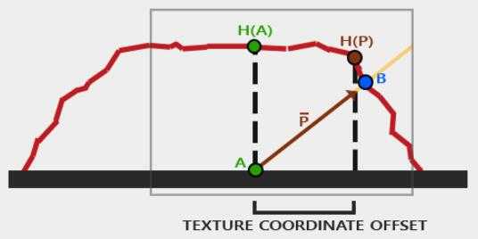
We then take this vector P¯P¯ and take its vector coordinates that align with the plane as the texture coordinate offset.
This works because vector P¯P¯ is calculated using a height value from the heightmap so the higher a fragment‘s height, the more it effectively gets displaced.
3、Parallax Mapping实现。
实例计算,会使用另一种模式。首先HeightMap 变成 DepthMap。DepthMap是HeightMap的取反。
其次,计算模型稍微变化:
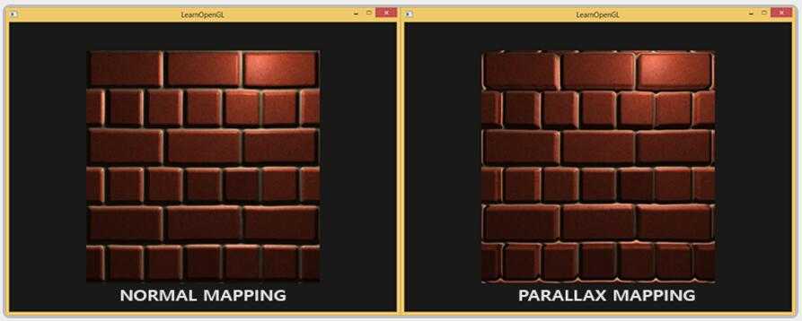
4、效果图。
5、Steep Parallax Mapping
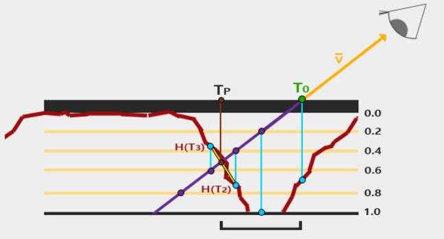
Steep Parallax Mapping is an extension on top of Parallax Mapping in that it uses the same principles, but instead of 1 sample it takes multiple samples to better pinpoint vector P¯P¯ to BB. This gives much better results, even with steep height changes as the accuracy of the technique is improved by the number of samples.
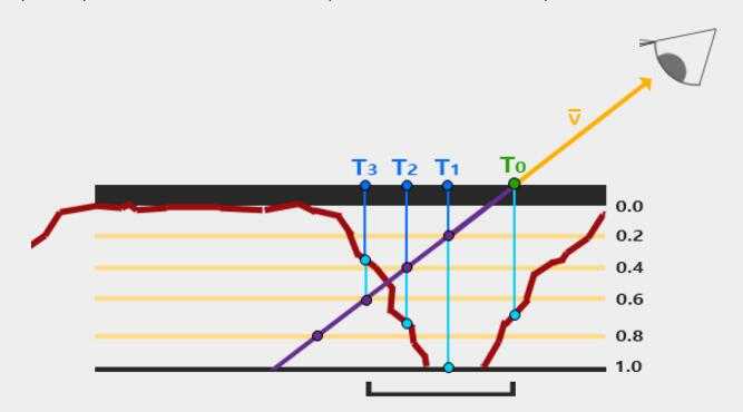
We traverse the depth layers from the top down and for each layer we compare its depth value to the depth value stored in the depthmap. If the layer‘s depth value is less than the depthmap‘s value it means this layer‘s part of vector P¯P¯ is not below the surface. We continue this process until the layer‘s depth is higher than the value stored in the depthmap: this point is then below the (displaced) geometric surface.
In this example we can see that the depthmap value at the second layer (D(2) = 0.73) is still lower than the second layer‘s depth value 0.4 so we continue. In the next iteration the layer‘s depth value 0.6 does become higher than the depthmap‘s sampled depth value (D(3) = 0.37). We can thus assume vector P¯ at the third layer to be the most viable position of the displaced geometry. We can then take the texture coordinate offset T3T3 from vector P3¯ to displace the fragment‘s texture coordinates. You can see how the accuracy increases with more depth layers.
6、Parallax Occlusion Mapping
Parallax Occlusion Mapping is based on the same principles as Steep Parallax Mapping, but instead of taking the texture coordinates of the first depth layer after a collision, we‘re going to linearly interpolate between the depth layer after and before the collision. We base the weight of the linear interpolation on how far the surface‘s height is from the depth layer‘s value of both layers.
As you can see it‘s largely similar to Steep Parallax Mapping with as an extra step the linear interpolation between the two depth layers‘ texture coordinates surrounding the intersected point. This is again an approximation, but significantly more accurate than Steep Parallax Mapping.
7、Relief Mapping
ReliefMap的基本思想和ParallaxMap完全一致:就是给通过光栅化计算出的贴图坐标加上一个偏移量来确定在凹凸的表面上这个坐标应该在的位置。区别是ParallaxMap仅仅是简单的根据高度沿着视方向移动UV,这样在深度高的时候就会出现严重的走样,但是ReliefMap则是通过确定视向量和凹凸表面的交点来计算偏移量的,如下图所示:
图中"点A"为光栅化计算出的贴图坐标,但因为我们的表面是凹下去的,所以摄像机看到的点应该是"点3",要实现这一点,我们就要计算出红色箭头所表示的那段偏移量,也就是要算出"点3"的坐标。
实现思想:
下面我们要做的就是确定一条从点A发出的方向为Vn的射线和这个凹凸表面的交点。这里要用到一些数值分析中的东西,就是二分法(Binary Search)和Linear Search(这东西我不知道它的中文应该是什么......)。
首先我们使用Linear Search方法确定这条射线最早同曲面所交点的大概位置,所谓LinearSearch其实就是沿着Vn方向按照一个指定的深度的步长"d"去找到那个第一个进入物体的位置所在的有根区间,如图所示:
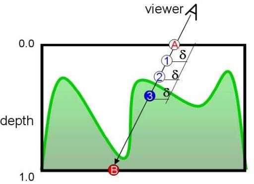
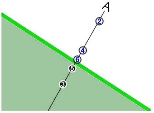
点2在表面外而点3在表面内,于是我们可以确认交点必定在点2和点3之间的这段区间上。下面我们就在这段区间中使用二分法来进一步确定交点的位置,如下图所示:
参考:
1、https://learnopengl.com/Advanced-Lighting/Parallax-Mapping
2、https://www.cnblogs.com/deepfar/archive/2008/05/31/1211276.html
标签:mes led 参考 poi long this like OWIN tps
原文地址:https://www.cnblogs.com/tekkaman/p/9045360.html