标签:style blog http color io os 使用 ar for
无线遥控就是利用高频无线电波实现对模型的控制。如天地飞(WFLY)的6通道2.4 GHz遥控器,一套200多块,具有自动跳频抗干扰能力,从理论上讲可以让上百人在同一场地同时遥控自己的模型而不会相互干扰。而且在遥控距离方面也颇具优势,2.4 GHz遥控系统的功率仅仅在100 mW以下,而它的遥控距离可以达到1km以上。
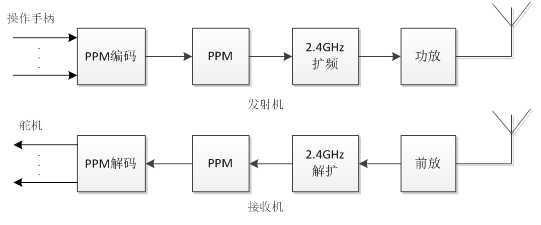
遥控器发射机、接收机原理
每个通道信号脉宽0~2ms,变化范围为1~2ms之间。1帧PPM信号长度为20ms,理论上最多可以有10个通道,但是同步脉冲也需要时间,模型遥控器最多9个通道。
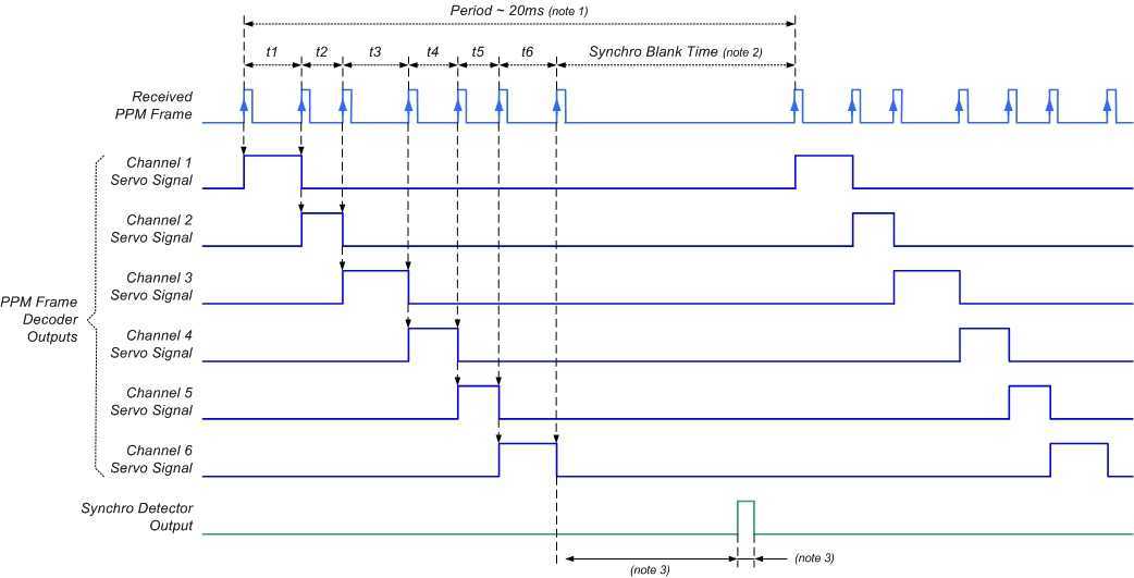
PPM格式
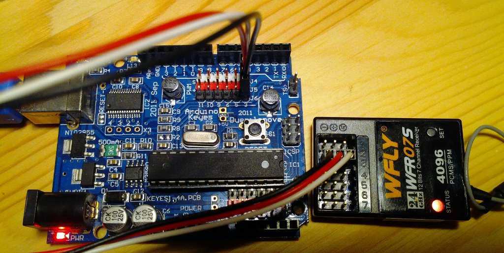
只连接了通道3(油门)
arduino要测量脉宽时间很简单。有专门的库函数pulseIn( )。问题在于这个库函数使用查询方式,程序在测量期间一直陷在这里,CPU利用率太低。因此下面代码采用中断方式,效率很高。
代码参考:http://arduino.cc/forum/index.php/topic,42286.0.html
Arduino源码:
//read PPM signals from 2 channels of an RC reciever
//http://arduino.cc/forum/index.php/topic,42286.0.html

//接收机两个通道分别接arduino的数字口2、3脚
//Most Arduino boards have two external interrupts: numbers 0 (on digital pin 2) and 1 (on digital pin 3).
//The Arduino Mega has an additional four: numbers 2 (pin 21), 3 (pin 20), 4 (pin 19), and 5 (pin 18).
int ppm1 = 2;
int ppm2 = 3;

unsigned long rc1_PulseStartTicks,rc2_PulseStartTicks;
volatile int rc1_val, rc2_val;

void setup() {

        Serial.begin(9600);

        //PPM inputs from RC receiver
        pinMode(ppm1, INPUT);
        pinMode(ppm2, INPUT);

        // 电平变化即触发中断
        attachInterrupt(0, rc1, CHANGE);
        attachInterrupt(1, rc2, CHANGE);
}

void rc1()
{
        // did the pin change to high or low?
        if (digitalRead( ppm1 ) == HIGH)
                rc1_PulseStartTicks = micros();    // store the current micros() value
        else
                rc1_val = micros() - rc1_PulseStartTicks;
}

void rc2()
{
        // did the pin change to high or low?
        if (digitalRead( ppm2 ) == HIGH)
                rc2_PulseStartTicks = micros();
        else
                rc2_val = micros() - rc2_PulseStartTicks;
}

void loop() {

        //print values
        Serial.print("channel 1:  ");
        Serial.print(rc1_val);
        Serial.print("        ");
        Serial.print("channel 2:  ");
        Serial.println(rc2_val);
}
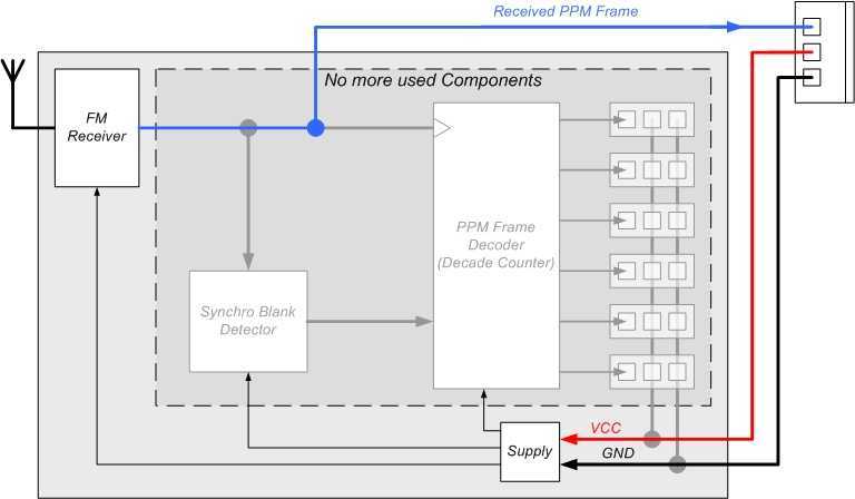
上述代码每个通道都要占用一个中断口。但是一般的Arduino只有数字口2、3具有中断功能,也就是说只能接两个通道。如果想使用更多的通道,就需要用mega了,mega有5个外部中断源。其实,还有一种简单办法可以用一个中断接收所有通道。这就是绕过接收机的解码电路,使用arduino直接对PPM信号解码。这种方式麻烦的地方是需要拆开接收机,把解码前的PPM信号引出来。
参考:http://diydrones.com/profiles/blogs/705844:BlogPost:38393
打开接收机后,寻找PPM信号接口有几种办法:
找到以后使用下面代码进行解码。此段代码使用查询方式,效率较低。更有效率的办法是使用两个中断。一个中断检测同步信号,另一个中断处理PPM信号。
Arduino源码:
//http://diydrones.com/profiles/blogs/705844:BlogPost:38393
#define channumber 4 //How many channels have your radio?
int value[channumber];

void setup()
{
        Serial.begin(57600); //Serial Begin
        pinMode(3, INPUT); //Pin 3 as input
}
void loop()
{
        while(pulseIn(3, LOW) < 5000){} //Wait for the beginning of the frame
        for(int x=0; x<=channumber-1; x++)//Loop to store all the channel position
        {
                value[x]=pulseIn(3, LOW);
        }
        for(int x=0; x<=channumber-1; x++)//Loop to print and clear all the channel readings
        {
                Serial.print(value[x]); //Print the value
                Serial.print(" ");
                value[x]=0; //Clear the value afeter is printed
        }
        Serial.println(""); //Start a new line
}
标签:style blog http color io os 使用 ar for
原文地址:http://www.cnblogs.com/stemon/p/3998596.html