标签:uart show 0x0d packet arc char rtb cas 频率
最近做课设,选了电力线通讯这种途径,经过百度google等一番查询,最终敲定了mi200e这块国产芯片。
然后淘宝买了拆机的成品,我拿回来把mcu拆了然后飞出通讯端口和stm8交互。现在串口两边可以通讯了,下一步就是重新绘制一块完整的pcb,然后制版,并实现响应功能。
先上ref:
http://search.eefocus.com/s?app_id=90&sub=1&q=mi200e
这是电路城搜索mi200e得出的结果,我主要参考第一篇,他在嘉立创还有发帖,点进去你就找得到了。
他使用stm8主控并绘制整块pcb,我则使用以前的stm8核心小板。由于mi200e常规供电为5v,稍稍更改核心板为5v供电做好。
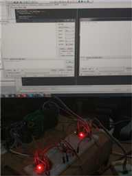
没有拍当时做的图片,上pcb和实物吧!
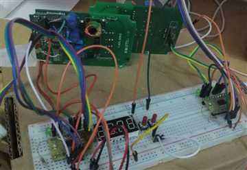
将右图放大后,可看到两块绿板,这两块就是成品模块,应用于智能抄表的。可看到左边那块上有一根小跳线,跳线右边哪里原来是块u,我用烙铁把他拆了。
不然stm8没法单独和mi200e通讯。至于为什么要跳那根线,我在网上恰好查到他的原理图,(应该是miartech官方的方案,然后抄的,原件丝印不同),mi200e的供电vdd受一个pmos控制,
所以直接将mos的g级接地。其实我买了两种,一共买了四块,连运费20+rmb。另一种的丝印是和原理图队上的。我后面会附上手头的资料。
两块板子背面其实有排针,原来用于接220v的,我直接把他们并联在一起,然后接了一根电源线。一方面因为我电源线紧张,另一方面固定在一块纸板上方便调试。
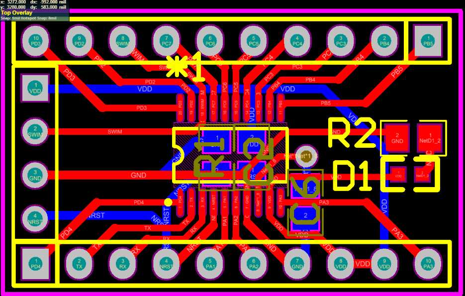
这是原理图,通讯接口是SPI,其中cs不能直接接地,因为数据是双向互传,并且不是单次传输。具体参考SPI接口flash的cs为什么不能直接接地吧。
我一开始想省io直接接地,结果调试的时候发现,自检过不了。
至于rst引脚,我把它接到stm8的nrst恰好可以使用,虽然官方应用笔记里面说要低电平1s后拉高。留待后面再测试吧。
这样就是4个io就能交互了。
然后我按照嘉立创那篇帖子里的方案做了,然后一直调试,发现他的程序我直接用不了,数据通。
然后我发现省略了crc校验初步数据能够发送,但是有毛病。
没办法,又看手册,看应用笔记。以及对比另一个c51版本的程序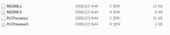
,这个程序从我给的链接里的第二篇可以下载到。但是这个只是驱动,应该就是这个产品用到的,但是没给全程序。我猜嘉立创那篇帖主
也是参考这个改的,因为驱动大体一致。我同时看笔记,以及两篇驱动,最后经过一番修改,然后下进去竟然就可以工作了。
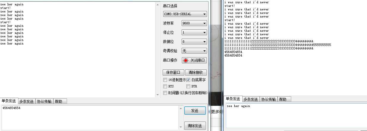
程序限制它64字节,对于一般应用足够了。
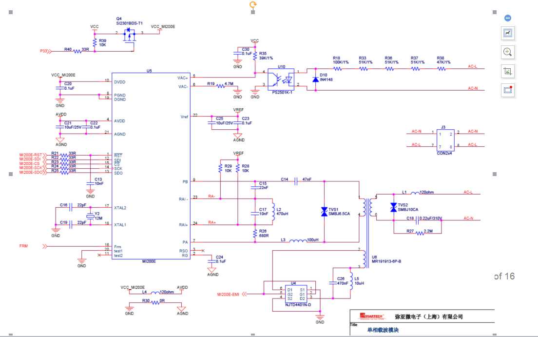
说一下这块芯片的发送过程,两个引导字节(一个字),一个固定字节,然后配置字节(速率和字长,字为单位)。到这里都是固定200/240bps速率(会因交流电频率不同而不同),之后的速率可自行配置,
程序里设定的是1600/1920bps。然后是以字为单位的数据(这里就是串口透传,由于是字对齐,所以必须是偶数字节,这里要注意!),最后一个字的CRC校验。
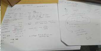
附上一张笔记图,看别人的代码真是不容易啊。这里双向能通讯了,后面再看要不要他程序的框架,如果要,还有更多细节要明白。
和硬件打交道,如果不懂的话,可能就是一个延时你就要消耗大把时间。所以需要日积月累!

  1 #include "stm8s.h"
  2 #include "config.h"
  3 #include "MI200E.h"
  4 #include "PLCProcess.h"
  5
  6 unsigned char g_cStatusReg;
  7 unsigned char g_cRecModCfgReg;
  8 unsigned short PLC_Word_Rec_Overtime;
  9 unsigned char    g_bRecv_Pkg_Flag;
 10 unsigned char g_CRC_H,g_CRC_L;
 11 unsigned char g_cPkg_Length = 0;
 12 unsigned char g_Pkg_Indication_Byte = 0;
 13 unsigned char g_cTrans_Step;
 14 unsigned char g_cRecv_Step;
 15 unsigned char g_cRecByte_H;
 16 unsigned char g_cRecByte_L;
 17 unsigned char g_cSend_Data_Length;
 18 unsigned char g_cSend_Byte_Cnt;
 19 unsigned char g_cRecv_Byte_Cnt;
 20 unsigned char g_Send_Buf[64];
 21 unsigned char g_Recv_Buf[64];
 22
 23
 24 void PLC_Send_Frame(unsigned char cWRData_H, unsigned char cWRData_L)
 25 {
 26   PLC_Write_Reg(PLCAddrWRSR,(g_cStatusReg&0x7F)); //Clear TI;Write Status Register:0x02
 27   MI200E_SCK_0;
 28   MI200E_CS_0;
 29   Write_SPI(PLCAddrWRTB0);    //Write Sending Byte Register 0:0x04
 30   Write_SPI(cWRData_H);
 31   Write_SPI(cWRData_L);
 32   MI200E_SCK_0;
 33   MI200E_CS_1;
 34 }
 35
 36 void PLC_RD_Recv_Word(void)
 37 {
 38   MI200E_SCK_0;
 39   MI200E_CS_0;
 40   Write_SPI(PLCAddrRDRB0);    //Read Receiving Byte Register 0:0x84
 41   g_cRecByte_H = Read_SPI();
 42   g_cRecByte_L = Read_SPI();
 43   MI200E_SCK_0;
 44   MI200E_CS_1;
 45 }
 46
 47 unsigned char PLC_Clear_EPF(void)
 48 {
 49   unsigned char cStatusByte;
 50
 51   cStatusByte = PLC_Read_Reg(PLCAddrRDSR);            //Read Status Register:0x82
 52   PLC_Write_Reg(PLCAddrWRSR, (cStatusByte&0xF5));    //Clear EPF Flag & CRC_Flag;Write Status Register:0x02
 53   return(cStatusByte);
 54 }
 55
 56
 57 void PLC_Transmit_Process(unsigned char* ptrData_Buffer)
 58 {
 59   unsigned char cStatusByte;
 60
 61   cStatusByte = PLC_Read_Reg(PLCAddrRDSR);    //Read status register
 62   if((cStatusByte&0x80) != 0x80)
 63   {
 64     return;
 65   }
 66   g_cStatusReg = cStatusByte;//**confirmed
 67   switch(g_cTrans_Step)
 68   {
 69   case 0:
 70     //Write Mode Cfg Reg, Code Length = 32, Data Rate = 200 bps;
 71     PLC_Write_Reg(PLCAddrWRMR, 0x0D); //**0x0d changed to 0x0c;diff:carriar freq:76.5->57.6khz
 72     PLC_Send_Frame(0xFF, 0xFF);     //First 2 Byte:0xFF 0xFF
 73     //Baud=1600bps + length(unit in words)
 74     g_Pkg_Indication_Byte = (0x00 + g_cSend_Data_Length/2 + 2);//**why finially +2??
 75     g_cTrans_Step = 1;
 76   break;
 77   case 1:
 78     //Initial CRC Bit;Write Status Register:0x02
 79     PLC_Write_Reg(PLCAddrWRSR,(g_cStatusReg & 0xFD));
 80     //Send Header Byte:0x1a & Packet Indication Byte
 81     PLC_Send_Frame(0x1A, g_Pkg_Indication_Byte);
 82     g_cTrans_Step = 2;
 83   break;
 84   case 2:
 85     //Write mode configuration;
 86     PLC_Write_Reg(PLCAddrWRMR,0x01);//0b0000  00--1600/1920bps  01--76.8khz**00 57.6k
 87     //Send 0x1f,0xff as MiarTech‘s PLC AMR Applications
 88     PLC_Send_Frame(0x1F,0xFF);//**the word??
 89     g_cTrans_Step = 3;
 90     g_cSend_Byte_Cnt = 0;
 91   break;
 92   case 3://Send Data(Unit in Word:16 Bytes)
 93     if(g_cSend_Byte_Cnt >= (g_cSend_Data_Length - 2))
 94     {
 95       g_cTrans_Step = 4;
 96     }
 97     PLC_Send_Frame(*ptrData_Buffer,*(ptrData_Buffer + 1));
 98     g_cSend_Byte_Cnt = g_cSend_Byte_Cnt + 2;//point to the next word
 99     delay_us(80);//delay 50us and read crc
100     g_CRC_H = PLC_Read_Reg(PLCAddrRD_CRC_H);
101     g_CRC_L = PLC_Read_Reg(PLCAddrRD_CRC_L);
102   break;
103   case 4://Send CRC Code:16 Bytes
104     PLC_Send_Frame(g_CRC_H, g_CRC_L);
105     g_cTrans_Step = 5;
106   break;
107   case 5://transmit finished   0x81
108     PLC_Write_Reg(PLCAddrWRMR, 0x81);    //Write mode configuration,
109     g_cRecByte_H        = 0;
110     g_cRecByte_L        = 0;
111     g_cRecv_Step        = 0x00;
112     PlcRunMode = PLCRX;
113     UartRunMode = IDLE;
114   break;
115   default:
116   break;
117   }
118 }
119
120
121 void PLC_Receive_Process(unsigned char* ptrData_Buffer)
122 {
123   unsigned char cStatusByte;
124   unsigned char CRC_Correct_Flag;
125 //  unsigned char temp,i;
126 //  static unsigned short cnt;
127
128
129   if(g_cRecv_Step == 0x10)//Receive Process Initialization OK
130   {
131     g_cRecModCfgReg = PLC_Read_Reg(PLCAddrRDRR);    //Read Receiving Mode Configuration Register(0x83)
132     cStatusByte = PLC_Read_Reg(PLCAddrRDSR);
133     if(g_cRecModCfgReg != 0x00)    //Have Received Spread Spectrum&Packet Length
134     {
135         PLC_Write_Reg(PLCAddrWRRR,0x00);        //Clear Receiving Mode Configuration Byte
136         g_cPkg_Length = (0x3f & g_cRecModCfgReg);    //Packet Length = g_cRecModCfgReg[5:0]
137         g_cRecv_Step = 0x01;
138         PLC_Word_Rec_Overtime = 0;
139     }
140     if(((cStatusByte & 0x30) != 0x30)||(PLC_Word_Rec_Overtime > 500)) //Receive Overtime >=1 Second
141     {
142         CRC_Correct_Flag = PLC_Clear_EPF();
143         g_cRecv_Step = 0x00;
144         return;
145     }
146   }
147   else if(g_cRecv_Step == 0x00)
148   {                            //0x81
149     PLC_Write_Reg(PLCAddrWRMR, 0x81);//bit[0]--bit[3]  00--1600/1920bps  01--76.8khz
150     cStatusByte = PLC_Read_Reg(PLCAddrRDSR);
151     g_cStatusReg = cStatusByte;
152     if((g_cStatusReg & 0x20 ) == 0x20)//Read Carrier Detected Flag
153     {
154       if((g_cStatusReg & 0x10) == 0x10)//Read Frame Indicate Flag
155       {
156           //Clear Receiving Mode Configuration Byte
157           //PLC_Write_Reg(PLCAddrWRRR, 0x00);//datasheet??
158           g_bRecv_Pkg_Flag = 0;//*(*?
159           g_cRecv_Step = 0x10;
160           PLC_Word_Rec_Overtime = 0;
161       }
162     }
163   }
164   else
165   {
166     cStatusByte = PLC_Read_Reg(PLCAddrRDSR);
167     g_cStatusReg = cStatusByte;
168
169      //Carrier Detected & Frame Indicate Flag is not Correct
170     if(((cStatusByte & 0x30) != 0x30)||(PLC_Word_Rec_Overtime > 500))
171     {
172       g_cRecv_Step = 0x00;
173       CRC_Correct_Flag = PLC_Clear_EPF();
174       return;
175     }
176     else
177     {
178       if((cStatusByte & 0x40) == 0x40)//Read Received Interrupt Flag.RI = 1:Received OK
179       {
180         PLC_Word_Rec_Overtime = 0;
181 //        if(cnt == 0)
182         {
183             PLC_Write_Reg(PLCAddrWRSR,((g_cStatusReg & 0xBF)|0x02)); //Clear RI Flag & Set MI200_CRC
184         }
185         switch( g_cRecv_Step )
186         {
187           case 0x01:    //Read 0x1f,0xff as MiarTech‘s PLC AMR Applications
188           {
189 //            cnt ++;
190 //            if(cnt > 20)
191 //            {
192 //              cnt = 0;
193 //              g_cRecv_Step = 0x00;
194 //              return;
195 //            }
196 //            temp = PLC_Read_Reg(PLCAddrRDSR);
197 //            if((temp&0x70) != 0x70)
198 //              return;
199 //            cnt = 0;
200 //
201             PLC_RD_Recv_Word();
202             if((g_cRecByte_H == 0x1F) && (g_cRecByte_L == 0xFF))
203             {
204               g_cRecv_Step = 0x02;
205               g_cRecv_Byte_Cnt = 0;
206             }
207             else
208             {
209               g_cRecv_Step = 0x00;
210               CRC_Correct_Flag = PLC_Clear_EPF();
211               return;
212             }
213           }
214           break;
215           case 0x02: //read user data
216           {
217 //            if(cnt == 0)
218 //            {
219 //                PLC_Write_Reg(PLCAddrWRSR,((g_cStatusReg & 0xBF )|0x02)); //Clear RI Flag & Set MI200_CRC
220 //            }
221 //            cnt ++;
222 //            if(cnt > 20)
223 //            {
224 //              cnt = 0;
225 //              g_cRecv_Step = 0x00;
226 //              return;
227 //            }
228 //            temp = PLC_Read_Reg(PLCAddrRDSR);
229 //            if((temp&0x70) != 0x70)
230 //              return;
231 //            cnt = 0;
232
233             if(g_cRecv_Byte_Cnt == (g_cPkg_Length - 3))    //1 for amr;1 for crc
234             {
235               g_cRecv_Step = 0x03;
236             }
237             PLC_RD_Recv_Word();
238
239             *(ptrData_Buffer + g_cRecv_Byte_Cnt) = g_cRecByte_H;
240             *(ptrData_Buffer + g_cRecv_Byte_Cnt + 1) = g_cRecByte_L;
241
242             g_cRecv_Byte_Cnt++ ;
243           }
244           break;
245           case 0x03: //读取CRC数据
246 //            cnt ++;
247 //            if(cnt > 20)
248 //            {
249 //              cnt = 0;
250 //              g_cRecv_Step = 0x00;
251 //              return;
252 //            }
253 //            temp = PLC_Read_Reg(PLCAddrRDSR);
254 //            if((temp&0x70) != 0x70)
255 //              return;
256 //            cnt = 0;
257
258             PLC_RD_Recv_Word();
259             CRC_Correct_Flag = PLC_Clear_EPF();
260             g_bRecv_Pkg_Flag = 1;
261             if ((CRC_Correct_Flag & 0x02) != 0x00) //CRC Flag Bit = 1;CRC is Correct
262             {
263               //串口发送
264               UartRunMode = TX;
265               unsigned char txlen;
266               txlen = (g_cPkg_Length-2)*2;
267               UsatrTxSub(g_Recv_Buf,txlen);
268               UartRunMode = IDLE;
269             }
270            g_cRecv_Step = 0x04;
271           break;
272           default:
273           break;
274         }
275       }
276     }
277   }
278 }
279
280
281 /*******************************************************************************
282 **                                  End Of File
283 *******************************************************************************/
主要修改的就是,这个文件了。后面有什么进展还会更新!
标签:uart show 0x0d packet arc char rtb cas 频率
原文地址:https://www.cnblogs.com/katachi/p/9693077.html
