标签:des style blog http color io os ar for
Methods, apparatus, and systems, including computer programs encoded on a computer storage medium, manage an address space. In some implementations, a method includes managing an allocation data structure for a memory, wherein the allocation data structure indicates groupings of memory space, each of the groupings having a different associated integer, and each of the groupings serving memory space in portions equal to a unit of memory space allocation times the associated integer for that grouping; receiving a request for allocation within the memory, wherein the request has an associated number of the unit of memory space allocation; and selecting one of the groupings from which to serve the request for allocation within the memory based on the associated number in comparison with values obtained using the different associated integers as an exponent.
BACKGROUND
The present disclosure describes systems and techniques relating to management of an address space for large caches.
A storage server system, such as a SAN (Storage Area Network) or NAS (Network-Attached Storage), has the primary purpose of providing shared storage that can be accessed by computers attached to the server through a network. A typical storage server is designed to serve as storage to many (10s or 100s or even 1000s) computers. What a computer attached to the storage server sees as a physically contiguous space is really composed of many physically disparate chunks of storage. The multiple physically disparate chunks of storage may be disks or disk partitions aggregated together as redundant array of inexpensive disks (RAID) devices.
A solid state disk (SSD) can be used as a large cache in front of a disk array. Most disk arrays or RAID controllers have some cache on them already to help with performance, but in comparison to an SSD these are relatively small. With SSD the memory available to cache can expand to 64-256 GB or more. This makes the likelihood of a cache miss significantly lower. In addition, using SSD as a large cache can help to fix a performance problem more cost effectively than adding more mechanical drives or replacing those drives with faster drives.
SUMMARY
The present disclosure includes systems and techniques for managing a cache address space associated with cache devices. According to an aspect of the described systems and techniques, a method includes receiving data to be cached in a cache address space associated with a cache memory. The cache address space includes two or more designated portions of the cache address space, such that each of the two or more designated portions has an associated minimum amount of data allowed to be cached therein. Additionally, the respective minimum amounts of the two or more designated portions are different from each other. The method also includes selecting a cache address for caching the received data from one of the two or more designated portions of the cache address space that has an associated minimum amount of data allowed to be cached therein being less than the received data. Further, the method includes caching the received data at the selected cache address, and accessing at least a subset of the data cached at the selected cache address.
These and other implementations can include one or more of the following features. The method can included determining the one of the two or more designated portions as a designated portion that has a largest associated minimum amount of data allowed to be cached therein from among ones of the two or more designated portions having respective minimum amounts of data allowed to be cached therein that are less than the received data.
In some implementations, the respective minimum amounts of data allowed to be cached in the two or more designated portions of the cache address space represent contiguous addresses within the two or more designated portions.
In some implementations, the respective minimum amounts of the two or more designated portions are larger than or equal to a predetermined amount of data, Furthermore, the method can include removing a part of the data cached at the selected cache address, such that the removed part is at least equal to the predetermined amount of data, whether or not the removed part of the data cached at the selected cache address is at least equal to the associated minimum amount of data allowed to be cached in the one of the two or more designated portions.
The minimum amounts of data allowed to be cached in the two or more designated portions of the cache address space can be respective integer multiples of the predetermined amount.
The one of the two or more designated portions of the cache address space can include one or more groups of contiguous addresses therein, and each group of the one or more groups includes two or more subgroups of chunks. A chunk is equal to the predetermined amount of data. Further, each of the two or more subgroups can be equal to the minimum amount of data allowed to be cached in the one of the two or more designated portions and can include an associated quantity of chunks. Selecting the cache address for caching the received data from the one of the two or more designated portions of the cache address space can be performed at least in part by using a data structure associated with a group included in the one of the two or more designated portions. The data structure is configured to indicate whether the two or more subgroups included in the group are occupied or partially occupied. Removing the part of the data cached at the selected cache address is performed at least in part by using the data structure associated with the group and another data structure associated with the group. The other data structure is configured to indicate whether the associated quantity of chunks included in each of the two or more subgroups of the group are free or occupied.
In some implementations, selecting the cache address for caching the received data from the one of the two or more designated portions of the cache address space further can include determining, within the one of the two or more designated portions, the group as having unoccupied subgroups among the two or more subgroups; identifying, based on the determined group‘s data structure, a quantity of subgroups within the determined group that are unoccupied and cumulatively equal to or larger than the received data, and based on the determined group‘s other data structure, another quantity of chunks corresponding to the identified quantity of subgroups. The other quantity of chunks cumulatively equal to the received data, and a combination of the identified quantities of subgroups and chunks represents the selected cache address. Selecting the cache address can further include updating the determined group‘s data structure to indicate that the identified quantity of subgroups are currently occupied; and updating the determined group‘s other data structure to indicate that the other identified quantity of chunks are currently occupied.
In some implementations, removing the part of the data cached at the selected cache address can further include determining, within the one of the two or more designated portions, the group corresponding to the part of the data cached at the selected address; updating the determined group‘s other data structure to indicate that a quantity of chunks corresponding to the removed part of the data cached at the selected cache address are currently unoccupied; and updating the determined group‘s data structure to indicate that another quantity of subgroups corresponding to the removed part of the data cached at the selected cache address are currently unoccupied. A subgroup is indicated to be unoccupied when all chunks included in the subgroup are unoccupied.
In some implementations, the method can also include determining that all subgroups of the determined group are unoccupied in response to said removing the part of the data cached at the selected cache address, and indicating that the group is unoccupied. In some implementations, the one of the two or more designated portions of the cache address space can include a collection of two or more occupied groups and another collection of two or more partially-occupied groups.
According to another aspect, the described subject matter can also be implemented in a system including a cache device communicatively coupled with a storage system. The system also includes one or more devices containing a management structure of a cache address space associated with the cache device. Further, the system includes a controller configured to maintain the management structure to include two or more designated portions of the cache address space, such that each of the two or more designated portions has an associated minimum amount of data allowed to be cached therein, and the respective minimum amounts of the two or more designated portions are different from each other. The controller is further configured (i) to receive data from the storage system to be cached in the cache address space associated with the cache device, (ii) to select a cache address from one of the two or more designated portions of the cache address space that has an associated minimum amount of data allowed to be cached therein being less than the received data, and (iii) to cache the received data at the selected cache address.
These and other implementations can include one or more of the following features. The controller can be configured to determine the one of the two or more designated portions as a designated portion that has a largest associated minimum amount of data allowed to be cached therein from among ones of the two or more designated portions having respective minimum amounts of data allowed to be cached therein that are less than the received data. In some implementations, the respective minimum amounts of data allowed to be cached in the two or more designated portions of the cache address space represent contiguous addresses within the two or more designated portions. In some implementations, the respective minimum amounts of the two or more designated portions are larger than or equal to a predetermined amount of data. Further, the controller can be configured to remove a part of the data cached at the selected cache address, such that the removed part is at least equal to the predetermined amount of data. The minimum amounts of data allowed to be cached in the two or more designated portions of the cache address space are respective integer multiples of the predetermined amount.
According to another aspect, the described subject matter can also be implemented in a system including a cache device communicatively coupled with a storage system. The system also includes a management structure of a cache address space associated with the cache device, such that the management data structure is loaded in a memory. Further, the system includes a controller configured to maintain the management structure loaded in the memory to include two or more designated portions of the cache address space. Each of the two or more designated portions has an associated minimum amount of data allowed to be cached therein, such that the respective minimum amounts of the two or more designated portions are different from each other and larger than or equal to a predetermined amount of data. Also, each of the two or more designated portions includes one or more groups of contiguous addresses therein. In addition, each group of the one or more groups includes two or more subgroups of chunks, where a chunk is equal to the predetermined amount of data. Each of the two or more subgroups is equal to a respective minimum amount allowed to be cached in each of the two or more designated portions and includes an associated quantity of chunks. Each group further has a data structure configured to indicate whether the two or more subgroups included in the associated group are occupied or partially occupied, and another data structure configured to indicate whether the associated quantity of chunks included in each of the two or more subgroups of the associated group are free or occupied. The controller is further configured to receive data from the storage system to be cached in the cache address space associated with the cache device. Furthermore, the controller is configured to select a cache address from a group of one of the two or more designated portions of the cache address space that has an associated minimum amount of data allowed to be cached therein that is less than the received data. Moreover, the selection of the cache address is based on an indication from a data structure associated with the group. Additionally, the controller is configured to remove a part of the data cached at the selected cache address, such that the removed part is at least equal to the predetermined amount of data. The part removal is based at least in part on respective indications from the data structure associated with the group, and from the other data structure associated with the group.
These and other implementations can include one or more of the following features. In some implementations, the one of the two or more designated portions of the cache address space can include a collection of two or more occupied groups and another collection of two or more partially-occupied groups.
In some implementations, selection of the cache address from the group of the one of the two or more designated portions of the cache address space includes a determination that the group has unoccupied subgroups; an identification, based on (i) the determined group‘s data structure, of a quantity of subgroups within the determined group that are unoccupied and cumulatively equal to or larger than the received data, and based on (ii) the determined group‘s other data structure, another identification of another quantity of chunks corresponding to the identified quantity of subgroups. The other quantity of chunks is cumulatively equal to the received data, and a combination of the identified quantities of subgroups and chunks represents the selected cache address. The selection of the cache address from the group further includes an update of the group‘s data structure to indicate that the identified quantity of subgroups are currently occupied, and another update of the group‘s other data structure to indicate that the other identified quantity of chunks are currently occupied.
In some implementations, removal of the part of the data cached at the selected cache address includes a determination, within the one of the two or more designated portions, of the group corresponding to the part of the data cached at the selected address; an update of the group‘s other data structure to indicate that a quantity of chunks corresponding to the removed part of the data cached at the selected cache address are currently unoccupied; and another update of the group‘s data structure to indicate that another quantity of subgroups corresponding to the removed part of the data cached at the selected cache address are currently unoccupied. A subgroup is indicated to be unoccupied when all chunks included in the subgroup are unoccupied. Additionally, the controller can be configured to determine that all subgroups of the group are unoccupied after the removal of the part of the data cached at the selected cache address, and to indicate that the group is unoccupied.
The described systems and techniques can be implemented in electronic circuitry, computer hardware, firmware, software, or in combinations of them, such as the structural means disclosed in this specification and structural equivalents thereof. This can include at least one computer-readable medium embodying a program operable to cause one or more data processing apparatus to perform operations described. Thus, program implementations can be realized from a disclosed method, system, or apparatus and apparatus implementations can be realized from a disclosed system, computer-readable medium, or method. Similarly, method implementations can be realized from a disclosed system, computer-readable medium, or apparatus and system implementations can be realized from a disclosed method, computer-readable medium, or apparatus.
The described systems and techniques can allow a large cache address space associated with a cache device to be managed with a very small memory overhead. For example, a 256 GB of cache address space can be managed in approximately 6.5 MB of memory by using the disclosed systems and methods. Additionally, unallocated regions of a given order in the cache address space can be found very quickly. For example, an allocation group for allocation can be found in a single lookup, while a first-set bit inside a current order bitmap can be obtained within 4 to 5 comparisons. In addition, even if some range from the cache address space has been allocated based on the disclosed management rules and structures, the allocated space can be freed in many different ways. This can allow a controller to allocate cache address space depending on user request but free/evict the same based on internal algorithms.
Details of one or more implementations are set forth in the accompanying drawings and the description below. Other features, objects and advantages may be apparent from the description and drawings, and from the claims.
DRAWING DESCRIPTIONS
FIG. 1 shows an example of a system for management of a cache address space associated with cache devices.
FIG. 2 shows of an example of a management structure for the cache address space associated with the cache devices.
FIG. 3 shows an example of a method for selecting an address in the cache address space associated with the cache devices based on the disclosed management structure.
FIGS. 4 and 5 show examples of substructures used in managing the cache address space associated with the cache devices.
FIG. 6 shows an example of a cache-allocation method based on the disclosed management structure.
FIG. 7 shows an example of a cache-freeing method based on the disclosed management structure.
Like reference symbols in the various drawings indicate like elements.
DETAILED DESCRIPTION
The systems and methods disclosed in this specification can be used for managing a cache address space associated with cache devices. More specifically, the methods are configured to minimize a total amount of data used for managing cache allocations. For example, most common cache allocations can be optimized in accordance with the disclosed methods by allocating maximum contiguous portions that are available in the cache address space. In this manner, the systems and techniques described herein can be implemented to manage allocation requests which tend to have few request sizes and target a cache memory space that has a large size. For example, the disclosed technology can be applied for managing block based SSD caches of direct attached storage, network attached storage (NAS) and storage area networks (SAN).
FIG. 1 shows an example of a system?100?for managing a cache address space associated with a cache device?110. The system?100?includes a controller?130?communicatively coupled with the cache device?110?and with a storage system?120. The controller?130?is configured to manage a cache address space associated with the cache device?110. In some implementations, the cache device?110?can be an SSD. In some implementations, the cache device can be flash memory. The storage system?120?can be direct attached storage (e.g., a hard drive), a NAS or a SAN.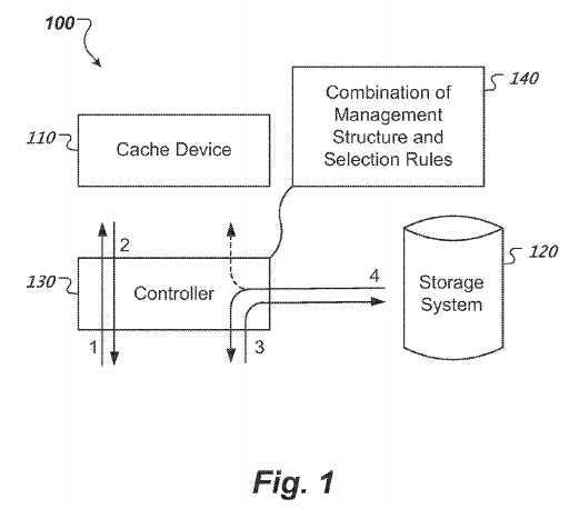
The system?100?can be implemented in multiple ways. In some implementations, the controller?130?can be part of the storage system?120?and can be configured to manage the cache memory space associated with a cache device?110?(e.g., an SSD) attached to the storage system?120. In some implementations, the controller?130?and the cache device?110?can be part of a caching appliance configured to be attached to the storage system?120. In some implementations, the cache device?110?and the controller?130?can be integrated within the storage system?120. For example, an SSD can be integrated either as a drive or a Peripheral Component Interconnect Express (PCIe) card inside of a server of the storage system?120, and a controller of the storage system?120?can be configured to operate the internal SSD. In some implementations, the cache device?110, the storage system?120?and the controller?130?can be operated separately from each other. For example, the functions of the controller?130?can be carried out by data processing apparatus, e.g., a central processing unit (CPU) associated with a computer system in communication with one or more SSD drives (representing the cache device?110) and with storage arrays of a storage system?120.
The controller?130?can be configured to handle requests for retrieving data from the cache device?110. The requests can be received from a data processing apparatus (not shown in FIG. 1) in communication with the controller?130. The requesting operations (1), (3) are represented by solid arrows. The request (1) can result in a cache-hit and, consequently, the controller?130?can retrieve (2) the requested data from the cache device?110. The retrieving operation (2) is represented by a solid-arrow and can include providing the retrieved data to the data processing apparatus, for instance. Additionally, the request (3) can result in a cache-miss and, consequently, the controller?130?can request the data from the storage system?120?instead of from the cache device?110. In this manner, the retrieving operation (4) can include providing the requested data to the data processing apparatus (represented by a solid-arrow) and caching the retrieved data to the cache device?110?(represented by a dashed-arrow).
Moreover, the controller?130?can be configured to select an address of the cache address space associated with the cache device?110?for caching the retrieved data. The selection can be performed by the controller?130?using a management structure for the cache address space and rules for selecting an address from the cache address space in accordance with the management structure. The combination?140?of the management structure and the rules can be maintained by the controller?130. For example, the combination?140?of the management structure and the rules can represent data structure(s), program code, or a combination thereof, each of which encoded in computer readable medium. In some implementations, the combination140?can be maintained in memory (e.g., random access memory, RAM) associated with the controller?130. In some implementations, the combination140?can be maintained in cache memory associated with the cache device?110. The technologies described in this specification can minimize a total amount of data used for maintaining the combination?140?of the management structure and the rules, and thus, reducing a memory overhead for managing the cache address space associated with the cache device?110.
FIG. 2 shows an example of a management structure?210?for a cache address space?215?associated with cache devices. Such a cache device?110?is described above in connection with FIG. 1. Additionally, the management structure?210?can be part of the combination?140?of the management structure and rules for selecting an address from the cache address space maintained by controller?130. The management structure?210?can represent one or more of data, data objects, data structures, programming code or combinations thereof. Further, the management structure can be encoded on computer readable media, e.g., associated with either of the controller?130, the cache device?110?or the storage system?120?as described above in connection with FIG. 1.
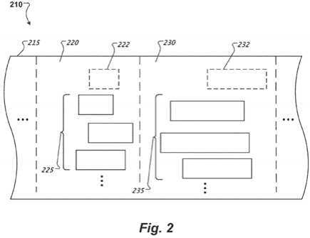
The management structure?210?includes multiple portions?220,?230, . . . of the cache address space?215. A portion from among the multiple portions220,?230, . . . of the cache address space?215?can be referred to, interchangeably, as an allocation slab. The dashed-lines used in FIG. 2 to separate the portions?220,?230, . . . of the cache address space?215?represent boundaries to separate different management rules corresponding to the portions220,?230, . . . , respectively, of the cache address space?215. For example, each of the multiple portions?220,?230, . . . has an associated minimum amount of data allowed to be cached therein, where the respective minimum amounts?222,?232, . . . of the multiple portions?220,?230, . . . are different from each other and correspond to contiguous ranges of the cache address space?215, respectively. The minimum amounts?222,?232, . . . are depicted as dotted-line rectangles. If the minimum amount?222?associated with the portion?220?is smaller than the minimum amount?232?associated with the portion?230, then a request for an allocation of cache memory larger or equal in size than the minimum amount?222?but smaller in size than the minimum amount?232?can be served from the portion?220?or from other portions having respective minimum amounts smaller than the requested allocation size, but cannot be served from the portion?230?nor from other portions having respective minimum amounts larger than the requested allocation size. In this specification, serving an allocation means selecting an address location and range within the cache address space associated with the cache device for caching, at the selected address, an amount of data having a size equal to a size of the selected range. For example, allocations?225?served from portion?220?correspond to respective contiguous address ranges within the portion?220?that have respective sizes satisfying the foregoing restrictions. As another example, allocations?235?served from portion?230?correspond to respective contiguous address ranges within the portion?230?that have respective sizes satisfying the foregoing restrictions. The above division of the cache address space?215?in the multiple portions?220,?230, . . . having specific properties is a logical division and not a physical one.
A minimum amount of data associated with a portion and allowed to be cached therein corresponds to 2m?contiguous chunks of the cache address space?215, where a chunk is the minimum unit of allocation and the exponent m=1, 2, . . . ; a chunk can have a predetermined size. For example, the chunk can be a multiple of a logical block. In some implementations, a size of the block is 4 K. In other implementations, the size of the block is 8 K. In addition, the exponent "m" corresponding to the quantity of chunks 2m?that forms the minimum amount of data associated with a portion and allowed to be cached therein represents the order of the portion, or the order of the allocation slab. For example, the minimum amount of data?222?allowed to be cached in the portion?220?of the cache address space?215?can be two chunks. Because 2 chunks=21, the order of the portion?220?in this case is m=1. As another example, the minimum amount of data?232?allowed to be cached in the portion?230?of the cache address space?215?can be four chunks. Because 4 chunks=22, the order of the portion?230?in this case is m=2. And so on and so forth.
Moreover, data that was cached at an address of the cache address space?215?associated with the cache device, based on the management structure210?and the allocation rules described above, can be freed in increment amounts equal to a chunk, regardless of the minimum amount associated with the portion of the cache address space?215?corresponding to the address of the data to be freed. For example, each of the allocations?235?served from the portion?232?(of order 2) is greater than or equal to the minimum amount?232?equal to four chunks. However, amounts of data equal to one, two or three chunks (i.e., smaller than the minimum amount?232?of data allowed to be cached in the portion?230) can be released from any of the allocations235?cached in the portion?230?of the cache address space?215?associated with the cache device. Freeing parts of cached data having sizes smaller than the corresponding allocation sizes, facilitates monitoring access patterns to the cached data and releasing the parts of the cached data that are accessed less frequently than neighboring cached data.
The respective sizes of the portions?220,?230, . . . can vary during operation of the cache device based on the data allocations to and data releases from each of the portions?220,?230, . . . of the cache address space?215. However, other characteristics of the portions?220,?230, . . . of the cache address space?215?associated with the cache device can be designated upon start-up of the cache device. The designation can include specifying the order of the portions corresponding to the management structure?210, i.e., specifying the maximum size (in terms of multiples of chunks) of the minimum amounts?222,?232, . . . of data allowed to be cached in the portions?220,?230, . . . , respectively. The management structure?210?can further include a management hierarchy described in detail below in connection with FIGS. 4 and 5. Such management hierarchy also can be designated along with the foregoing designation of the portions?220,?230, . . . of the cache address space?215?associated with the cache device upon start-up of the cache device.
FIG. 3 shows an example of a method?300?for selecting an address in the cache address space associated with the cache devices based on the management structure disclosed in this specification. In the example illustrated in FIG. 1, the method?300?can be performed by the controller?130?in accordance with the management structure?210?described above in connection with FIG. 2. At?310, data from a storage system (e.g.,?120) is received for caching in the cache address space associated with the cache device (e.g.,?110). For example, allocations can be called having respective page sizes that are multiples of a chunk size. As described above, the chunk size can be equal to the size of a block in the logical address space associated with the cache device.
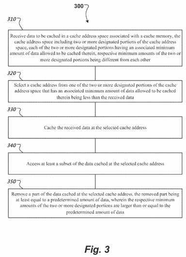
At?320, a cache address is selected, in response to receiving the data for caching. The selection is performed, at?320, from one of the two or more designated portions of the cache address space that has an associated minimum amount of data allowed to be cached therein being less than or equal to the received data. In this context, the selected cache address represents an address offset (start) and a contiguous address range (length) within the one of the two or more designated portions of the cache address space. In the example illustrated in FIG. 2, the portions?220,?230, . . . of the cache memory space can be designated to form, at least in part, the management structure?210. In this example, if the size of the received data to be cached has a cumulative size of at least four chunks, then the controller?130?can select the cache address from the portion?230, which has an associated minimum amount?232?equal to four chunks, or from the portion?220, which has an associated minimum amount?222?equal to two chunks.
In some implementations, the method?300?can include determining a designated portion that has a largest associated minimum amount of data allowed to be cached therein from among ones of the two or more designated portions having respective minimum amounts of data allowed to be cached therein that are less than the received data. In the example illustrated in FIG. 2, if the size of the received data to be cached has at least a cumulative size of four chunks, then the controller?130?selects the cache address for caching the received data from the portion?230?and not from the portion?220, because the minimum amount?232?(four chunks) associated with the portion?230?is larger than the minimum amount?222?(two chunks) associated with the portion?220.
At?330, the received data is cached at the selected cache address. In the example illustrated in FIG. 2, the selected address is within the portion?230, and thus, the received data can be cached in this portion along with the previous allocations?235?served from the portion?230?of the cache memory space.
At?340, at least a subset of the data cached at the selected cache address is accessed. In the example illustrated in FIG. 1, the data cached at the selected address is accessed (1) and then retrieved (2) at the request of a data processing apparatus. In addition, a temporal pattern of accesses to and a spatial pattern of accesses around the selected address can be monitored. Based on the monitored temporal and spatial patterns related to the selected address, removal of at least a part of the data cached at the selected address can be triggered.
At?350, a part of the data cached at the selected cache address can be removed. The removal can be responsive to the monitored temporal and spatial patterns described above. The removed part is at least equal to a predetermined amount of data whether or not the removed part of the data cached at the selected cache address is at least equal to the associated minimum amount of data allowed to be cached in the one of the two or more designated portions. The predetermined amount of data, representing the increment amount of data that can be freed from the cache address space, can be designated upon start-up of the cache device, for instance, along with the designation of the minimum amounts of data allowed to be cached in respective portions of the cache address space. Further, the predetermined amount of data can be specified to be a chunk that includes one or more logical blocks of the cache device.
In the example illustrated in FIG. 2, a size of a given data cached at the selected address within portion?230?can be equal to sixteen chunks. For instance, it may be determined that a part (e.g., having a size of three chunks) of the given data cached at the selected address is accessed more sparsely (either temporally or spatially) than other parts of the data cached at the selected address. In response to this determination, the controller?130can free the sparsely accessed part of the cached given data.
FIG. 4 shows an example of a substructure?420?for managing the cache address space associated with the cache devices. The substructure?420?can be referred to, interchangeably, as an allocation slab. In the example illustrated in FIG. 2, the allocation slab?420?corresponds to one of the multiple portions?220,?230, . . . of the cache address space?215?associated with the cache device in accordance with the management structure?210. As described above in connection with FIG. 2, sizes of allocations served from the allocation slab?420?are larger than or equal to an associated minimum amount of data allowed to be cached therein. For example, if the allocation slab?420?corresponds to the designated portion?230, the allocations?235served from the allocation slab?420?each has a size larger than or equal to the minimum amount?232, e.g., four chunks.
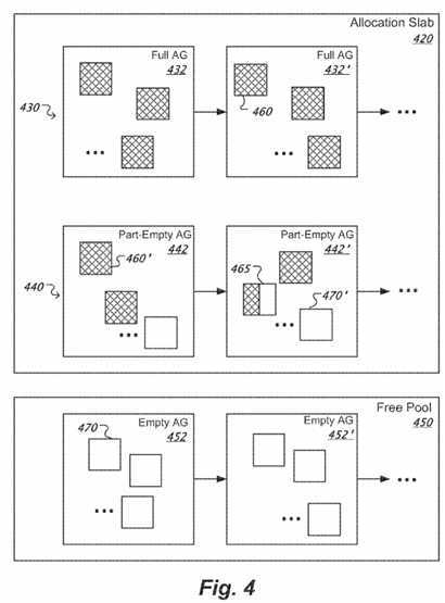
In order to manage a part of the cache address space corresponding to the allocation slab?420, another substructure called an allocation group can be introduced. In this manner, the allocation slab?420?includes one or more allocation groups?432,?432′,?442,?442′, . . . ; additionally, an order of the allocation groups?432,?432′,?442,?442′, . . . included in the allocation slab?420?is equal to the order of the allocation slab?420. Equivalently, allocations served from any of the allocation groups?432,?432′,?442,?442′, . . . included in the slab?420?have a size larger than or equal to the minimum amount of data allowed to be cached within the slab?420. As the allocation slabs are designated to have different orders, an allocation group of order "m" that is part of an allocation slab of order "m" cannot also be part of another allocation slab of order "n≠m", because the order "m" of the allocation group would not match the order "n" of the other allocation slab, although a match should occur if the allocation group of order "m" also were part of the other allocation slab of order "n".
Each of the allocation groups?432,?432′,?442,?442′, . . . included in the allocation slab?420?corresponds to a contiguous address range within the part of cache address space associated with the allocation slab?420. Specifically, a predetermined quantity "N" of subgroups each formed from 2m?contiguous chunks (where "m" is the order of the slab?420) is contained in each of the allocation groups?432,?432′,?442,?442′, . . . included in the allocation slab420. The predetermined quantity "N" can be designated when defining the management structure?210, for instance. Management of the "N" subgroups in each of the allocation groups?432,?432′,?442,?442′, . . . included in the allocation slab?420?is described in detail below in connection with FIG. 5.
In operation, the allocation groups?432,?432′, . . . are considered occupied (full) when all "N" subgroups of each of the allocation groups?432,?432′, . . . are occupied. A subgroup is occupied when all 2m?chunks of the occupied subgroup?460?have been served to one or more allocations. Examples of occupied subgroups?460,?460′, . . . are depicted by hashed-rectangles. The allocation groups?442,?442′, . . . are considered partially-occupied (part-free) when at least some but not all of the "N" subgroups of each of the allocation groups?442,?442′, . . . are partially-occupied or unoccupied. A subgroup is partially-occupied when less than all 2m?chunks of the partially-occupied subgroup have been served to one or more allocations. An example of a partially-occupied subgroup?465?is depicted by a partially-hashed-rectangle.) A subgroup is unoccupied when none of the 2m?chunks of the unoccupied subgroup has been served to one or more allocations. Examples of unoccupied subgroups?470,?470′, . . . are depicted by unfilled-rectangles.
Moreover, the allocation groups?432,?432′,?442,?442′, . . . included in the allocation slab?420?can be organized based on whether they are occupied or partially-occupied. In this manner, the allocation slab?420?contains two collections?430,?440?of allocation groups. In some implementations, the collections represent lists (e.g., linked lists.) In some implementations, the collections represent tables. One of the two collections is an occupied collection?430?to keep track of the allocation groups?432,?432′, . . . with all subgroups occupied. For example, the controller?130?can skip the occupied collection?430?when searching through the allocation slab?420?for partially-occupied allocation groups from which to serve allocations. Another one of the two collections is a partially free collection?440?to keep track of allocation groups?442,?442′, . . . which are partially occupied. For example, the controller?130?can serve allocation requests from allocation groups in the partially free collection?440. Rules related to searching the two collections430,?440?when serving allocation requests are described below in connection with FIG. 6.
In addition, each of the two collections?430,?440?has an associated index such that entries of the associated index represent identifiers of the allocation groups that are part of each of the two collections?430,?440. Thus, given an offset of a cache address, an allocation group that corresponds to the cache address can be determined by searching the respective indexes of the two collections?430,?440.
Apart from substructures like the allocation slabs?420,?220,?230, . . . , and the allocation groups?432,?432′,?442,?442′, . . . therein, the management structure?210?can include a pool of free allocation groups?450?that stores allocation groups?452,?452′, . . . which are completely free. Any of the free allocation groups?452,?452′, . . . maintained as part of the free pool?450?can be exported from the free pool?450?to an allocation slab from among the multiple allocation slabs?420,?220,?230, . . . associated with the cache address space?215?when all allocation groups contained in the allocation slab are fully occupied. Moreover, an allocation group from among the multiple allocation slabs?420,?220,?230, . . . can be imported into the free pool?450?when the allocation group becomes unoccupied (e.g., upon freeing all the "N" chunks included in the allocation group.) An order "m" is not being defined for the free pool?450, and thus, an allocation group from among the allocation groups?452,?452′, . . . maintained as part of the free pool?450?can acquire the order "m" of an allocation slab from among the multiple allocation slabs?420,?220,?230, . . . upon exporting the allocation group from the free pool?450?to the allocation slab.
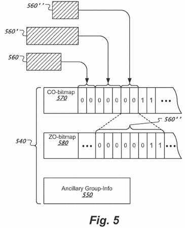
FIG. 5 shows another example of a substructure?540?for managing the cache address space associated with the cache devices. In the example illustrated in FIG. 4, the substructure?540?corresponds to an allocation group from among the partially-occupied allocation groups?442,?442′, . . . ; the allocation group?540?corresponds to a contiguous address range within the part of cache address space associated with an allocation slab of order "m" (e.g., allocation slab?420.) Moreover, "N" subgroups each formed from 2m?contiguous chunks (where "m" is the order of the allocation slab) are contained in the allocation group?540. For example, the allocation group?540?is contained in an allocation slab of order m=2. Accordingly, each of the "N" subgroups of chunks in the allocation group?540?has four chunks (4=22,) and therefore allocations of no less than four chunks in size can be served from the allocation group?540. Additionally in this example, there are N=32 subgroups of four chunks in the allocation group?540.
The allocation group?540?has an allocation group identifier, AG_ID. The AG_ID can be used to determine the range of cache pages mapped by the allocation group?540. For example, an allocation group?540?can contain 128 chunks, where each chunk has 16 K. Such allocation group?540corresponds to a range of cache address space of 2044 K (=2 MB.) Then, the allocation group?540?having an AG_ID=10 corresponds to a region of the cache address space from 20 MB to 22 MB.
Selecting a cache address for caching data within the contiguous part of the cache address space corresponding to the allocation group?540?can be performed at least in part by using a data structure?570?associated with the allocation group?540. The data structure?570?is configured to indicate whether the "N" subgroups included in the allocation group?540?are occupied or partially occupied. The data structure?570?can be implemented as a bitmap and can be referred to, interchangeably, as a current-order (CO) bitmap. For instance, the CO-bitmap?570?contains "N" bits, such that a bit value=1 corresponds to an associated subgroup from among the 2m?contiguous chunks that is available for allocation, i.e., is free, and a bit value=0 corresponds to an associated subgroup from among the 2m?contiguous chunks that is unavailable for allocation, i.e., is allocated. Accordingly, the CO-bitmap?570?provides a subgroup-level representation of occupancy for the allocation group?540.
Further, removing a part of data cached at a cache address within the contiguous part of the cache address space corresponding to the allocation group?540?can be performed at least in part by using the data structure?570?associated with the group?540?and another data structure?580?associated with the group?540. The other data structure?580?is configured to indicate whether the 2m?associated chunks included in each of the "N" subgroups of the allocation group?540?are free or occupied. The data structure?580?can be implemented as a bitmap and can be referred to, interchangeably, as a zero-order (ZO) bitmap. For instance, the ZO-bitmap?580?contains N×2m?bits, one bit for each of the chunks included in the allocation group?540, such that a bit value=1 corresponds to an associated chunk that is free from among the 2m?contiguous chunks in a respective subgroup, and a bit value=0 corresponds to an associated chunk that is allocated from among the 2m?contiguous chunks in the respective subgroup. Accordingly, the ZO-bitmap?580provides a chunk-level representation of occupancy for the allocation group?540.
In the example illustrated in FIG. 5, the order associated with the allocation group?540?is m=2, and there are N=32 subgroups of four chunks in the allocation group?540. Accordingly, the CO-bitmap?570?has 32 bits, one for each of the N=32 subgroups of four chunks in the allocation group?540, and the ZO-bitmap?580?has 128 bits, one for each of the 32×22?chunks in the allocation group?540. In this example, the CO-bitmap?570?can be stored in 4 bytes of memory and the ZO-bitmap?580?can be stored in 16 bytes of memory. Even if the CO-bitmap?570?had 128 bits, corresponding to an allocation group?540?of order m=0, the CO-bitmap?570?and the ZO-bitmap?580?together need not require any more than 32 bytes to store.
FIG. 5 also shows an example of mapping between cached data?560,?560′ and?560″ corresponding to respective allocations served within the allocation group?540?and the combination of the CO-bitmap?570?and the ZO-bitmap?580?associated with the allocation group?540. For example, the cached data560?has a size of 8 chunks and corresponds to an allocation of two subgroups of the allocation group?540. Accordingly, the cached data?560?occupies two (the first and second) subgroups of the 32 subgroups contained in the allocation group?540, and equivalently, the cached data?560?occupies eight (the first eight) chunks (2 subgroups×4 chunks per subgroup) of the 128 chunks of the allocation group?540. Therefore, the cached data?560corresponds to the first two bits of the CO-bitmap?570, and to the first eight bits of the ZO-bitmap?580. To indicate that the first and second subgroups of the allocation group?540?are occupied, the first two bits of the CO-bitmap?570?are set to 0 (shown in FIG. 5), and the first eight bits of the ZO-bitmap580?are also set to 0 (not shown in FIG. 5). As another example, the cached data?560′ has a size of 12 chunks and correspond to another allocation of three of subgroups of the allocation group?540. Accordingly, the cached data?560′ occupies three (the 3rd?through 5th) subgroups of the 32 subgroups contained in the allocation group?540, and equivalently, the cached data?560′ occupies twelve (the 9th?through 20th) chunks (3 subgroups×4 chunks per subgroup) of the 128 chunks of the allocation group?540. Therefore, the cached data?560′ corresponds to the 3rd?through 5th?bits of the CO-bitmap?570, and to the 9th?through 20th?bits of the ZO-bitmap?580. To indicate that the 3rd?through 5th?subgroups of the allocation group?540?are occupied, the 3rdthrough 5th?bits of the CO-bitmap?570?are set to 0 (shown in FIG. 5), and the 9th?through 20th?bits of the ZO-bitmap?580?are also set to 0 (not shown in FIG. 5).
Cached data?560″ has a size of 6 chunks and corresponds, for instance, to an allocation of two subgroups (or eight chunks) of the allocation group?540followed by a release (free) of two chunks. Accordingly, the cached data?560″ occupies six (the 21st?through 26th) chunks of the 128 chunks of the allocation group?540, and equivalently, the cached data?560″ partially occupies two (the 6th?and half of the 7th) subgroups of the 32 subgroups contained in the allocation group?540. Therefore, the cached data?560″ corresponds to the 6th?and 7th?bits of the CO-bitmap?570, and to the 21st?through 26th?bits of the ZO-bitmap?580. To indicate that the 6th?and 7th?subgroups of the allocation group?540?are not free, the 6th?and 7th?bits of the CO-bitmap?570?are set to 0 (show in FIG. 5). However, to indicate that the 21st?through 26th?chunks of the allocation group?540?are occupied and the 27th?and 28th?chunks of the allocation group?540?are free, the 21st?through 26th?bits of the ZO-bitmap?580?are set to 0, but the 27th?and 28th?bits of the ZO-bitmap?580?are maintained at 1 (shown in FIG. 5).
The allocation group?540?further includes ancillary information?550?used to store various characteristics of the allocation group?540. The ancillary information?550?includes the current order "m" of the allocation group. As described above, the order of the allocation group?540?corresponds to the order of the allocation slab that contains the allocation group?540. In the example illustrated in FIG. 5, the current order is m=2. There is 1 byte dedicated for storing the current order information. A quantity of free subgroups (or free buddies) of 2m?chunks is also included in the ancillary information?550. In the current example, the allocation group?540?has 32 subgroups out of which 7 are currently occupied as indicated in the CO-bitmap570. Hence, the number of free subgroups in the allocation group?540?is 25. There is 1 byte dedicated for storing information about the quantity of free subgroups. The ancillary information?550?further includes a reference to the allocation slab (e.g., a list head to the associated link list in the allocation slab). As described above in connection with FIG. 4, the allocation group?540?can be part of one of two linked lists?430,?440?associated with slab?420depending on whether the allocation group?540?is occupied or partially occupied, and 8 bytes can be dedicated for storing information about the associated link list of the corresponding allocation slab. Furthermore, the ancillary information?550?can include spin-lock information. The spin-lock information specifies whether the allocation group?540?is currently locked because data is currently cached to or freed from addresses associated with the allocation group?540. There are 4 bytes dedicated for the spin-lock information. The start index of the first chunk included in the allocation group?540can also be stored in the ancillary information?550. There are 4 bytes dedicated for information about the start index of the first chunk. The ancillary information?550?can also include flags for specifying particular characteristics (if any) of the allocation group?540. There are 2 bytes dedicated for storing information about the flags associated with the allocation group?540.
In all, the ancillary information?550?associated with the allocation group?540?can be stored in a total of 20 bytes. In addition, as noted above, the CO-bitmap?570?and the ZO-bitmap?580?associated with the allocation group?540?together need not require any more than 32 bytes to store. Accordingly, the cumulative overhead for managing an allocation group?540?having 128 chunks of 16 K per chunk is 52 bytes or 3.25 bits per chunk. For example, a cache address space having a size of 256 GB can be managed in approximately 6.5 MB of memory by using the disclosed systems and methods (e.g., the combination?140?of the management structure and rules implemented with 128 chunks per allocation group and a 16 K chunk size.)
FIG. 6 shows an example of a cache-allocation method?600?based on the disclosed management structure. In the example shown in FIG. 1, the method600?can be performed by the controller?130?and can be implemented as part of system?100. Moreover, the method?600?can be used in combination with method?200?for selecting a cache address from the one of the two or more designated portions (e.g., allocation slabs?420,?220,?230, . . . ) of the cache address space?215?associated with a cache device (e.g.,?110) for caching data received from a storage system (e.g.,?120). The received data to be cached at the selected cache address has a size of multiple chunks. An allocation slab from which to select the cache address is identified as having the highest order "m", such that the size of the data to be cached is larger than or equal to 2m?chunks (corresponding to the minimum amount allowed to be cached in the identified slab), as described above in connection with FIG. 3.
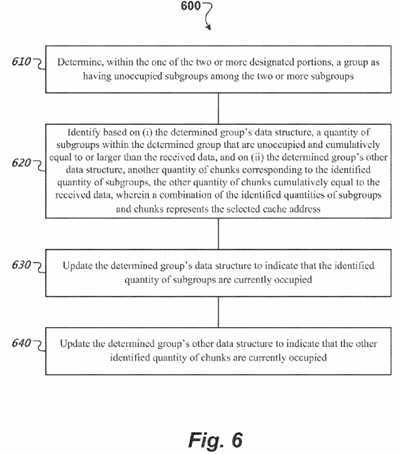
At?610, an allocation group having unoccupied subgroups is determined within the identified allocation slab. If no partially occupied allocations groups (e.g.,?442,?442′, . . . ) are available in the identified slab (e.g.,?420) then an allocation group can be imported from a pool of free allocation groups (e.g., free pool?450.) If the free pool?450?is empty, then the determination at?610?can be retried from a lower order allocation slab. If lower order allocation slabs are not available, because the identified allocation slab is the lowest order allocation slab, then cache eviction from a cache address corresponding to the identified slab can be triggered. However, if the identified allocation slab (e.g.,?420) has at least one partially occupied allocation group (e.g., one of?442,?442′, . . . from the partially free collection?440?of allocation groups) then the allocation is served from that allocation group.
At?620, a quantity of subgroups within the determined allocation group that are unoccupied and cumulatively equal to the received data is identified based on the allocation group‘s data structure (e.g., CO-bitmap?570) and another quantity of chunks corresponding to the identified quantity of subgroups is further identified based on the determined allocation group‘s other data structure (e.g., ZO-bitmap?580). The other quantity of chunks cumulatively equals the size of the received data, such that a combination of the identified quantities of subgroups and chunks represents the selected cache address. For example, the CO-bitmap is used to find a first free entry of current order corresponding to a subgroup of the determined allocation group (e.g., respective subgroup entries for allocations?560,?560′,?560″ in CO-bitmap?570.) Then the ZO-bitmap is used to identify sub order or unaligned free chunks if necessary (e.g., chunk entries for allocation?560″ in ZO-bitmap?580.)
At?630, the determined group‘s data structure (e.g., CO-bitmap?570) is updated to indicate that the identified subgroups are currently occupied, and at640, the determined group‘s other data structure (e.g., ZO-bitmap?580) is updated to indicate that the identified chunks are currently occupied. For example, once the first "set" bit (=1) is identified in CO-bitmap, the identified bit is toggled to 0 and corresponding single chunk bits in ZO-bitmap are also toggled to zero.
FIG. 7 illustrates a method?700?for releasing cached data based on the claimed management scheme. In the example shown in FIG. 1, the method?700can be performed by the controller?130?and can be implemented as part of system?100. Moreover, the method?700?can used in combination with method200?for removing a part of data cached at a selected cache address. Requests for cache frees include a start-offset and length of range for the part of cached data to be freed. The start-offset of the data to be freed is aligned with a chunk and the range of the data to be freed is a multiple of chunks.
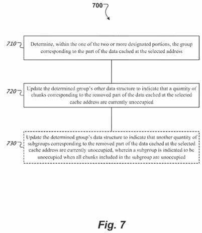
At?710, the allocation group corresponding to the part of the data to be freed at the selected address is determined within an allocation slab. For example, the identifier of the allocation group can be determined by dividing (bit shift, e.g., right shift of 5) the received start offset expressed in terms of the chunk identifier by the quantity of chunks per allocation group. As another example, the identifier of the allocation group can be determined by a right shift of 7 performed on the received start offset of the cache address space.
At?720, the determined allocation group‘s other data structure (e.g., ZO-bitmap?580) is updated to indicate that a quantity of chunks corresponding to the removed part of the data cached at the selected cache address is currently unoccupied. For example, the bits in the ZO-bitmap of the determined allocation group, starting with the bit associated with the start-offset chunk and including bits corresponding to a quantity of chunks equivalent to the range of data to be freed, are set to 1.
Optionally at?730, the determined allocation group‘s data structure (e.g., CO-bitmap?570) can be updated to indicate that subgroup(s) corresponding to the removed part of the data cached at the selected cache address are currently unoccupied. Specifically, a subgroup is indicated to be unoccupied when all chunks included in the subgroup are unoccupied. For example, if the quantity of bits toggled to?1?in the ZO-bitmap is larger than or equal to 2m, where m is the order of the determined allocation group, and if the bits toggled to 1 in the ZO-bitmap are aligned with a bit in the CO-bitmap, then a subgroup of 2m?chunks that corresponds to the aligned bit in the CO-bitmap is indicated to be unoccupied by setting the latter to 1.
The method?700?can optionally include determining that all subgroups of the determined allocation group are unoccupied in response to removing the part of the data cached at the selected cache address, and indicating that the group is unoccupied in response to the determination. For example, if freeing the part of the data at the selected address results in the identified allocation group being totally free, then the free allocation group can be exported to the free pool of allocation groups (e.g., 250.) Once part of the free pool, the unoccupied allocation group can be managed along with other free allocation groups?452,?452′, . . . as described above in connection with FIG. 5.
A few implementations have been described in detail above, and various modifications are possible. The disclosed subject matter, including the functional operations described in this specification, can be configured in electronic circuitry, computer hardware, firmware, software, or in combinations of them, such as the structural means disclosed in this specification and structural equivalents thereof, including potentially a program operable to cause one or more data processing apparatus to perform the operations described (such as a program encoded in a computer-readable medium, which can be a memory device, a storage device, a machine-readable storage substrate, or other physical, machine-readable medium, or a combination of one or more of them).
The term "data processing apparatus" encompasses all apparatus, devices, and machines for processing data, including by way of example a programmable processor, a computer, or multiple processors or computers. The apparatus can include, in addition to hardware, code that creates an execution environment for the computer program in question, e.g., code that constitutes processor firmware, a protocol stack, a database management system, an operating system, or a combination of one or more of them.
A program (also known as a computer program, software, software application, script, or code) can be written in any form of programming language, including compiled or interpreted languages, or declarative or procedural languages, and it can be deployed in any form, including as a standalone program or as a module, component, subroutine, or other unit suitable for use in a computing environment. A program does not necessarily correspond to a file in a file system. A program can be stored in a portion of a file that holds other programs or data (e.g., one or more scripts stored in a markup language document), in a single file dedicated to the program in question, or in multiple coordinated files (e.g., files that store one or more modules, sub programs, or portions of code). A program can be deployed to be executed on one computer or on multiple computers that are located at one site or distributed across multiple sites and interconnected by a communication network.
While this specification contains many specifics, these should not be construed as limitations on the scope of what may be claimed, but rather as descriptions of features that may be specific to particular implementations. Certain features that are described in this specification in the context of separate implementations can also be configured in combination in a single implementation. Conversely, various features that are described in the context of a single implementation can also be configured in multiple implementations separately or in any suitable subcombination. Moreover, although features may be described above as acting in certain combinations and even initially claimed as such, one or more features from a claimed combination can in some cases be excised from the combination, and the claimed combination may be directed to a subcombination or variation of a subcombination.
Similarly, while operations are depicted in the drawings in a particular order, this should not be understood as requiring that such operations be performed in the particular order shown or in sequential order, or that all illustrated operations be performed, to achieve desirable results. In certain circumstances, multitasking and parallel processing may be advantageous. Moreover, the separation of various system components in the implementations described above should not be understood as requiring such separation in all implementations.
Other implementations fall within the scope of the following claims.
SRC=http://www.freepatentsonline.com/8862838.html
Low overhead memory space management
标签:des style blog http color io os ar for
原文地址:http://www.cnblogs.com/coryxie/p/4038957.html