标签:bottom 插入 type 最好 gre must direction eve cte
http://gazebosim.org/tutorials?tut=model_structure&cat=build_robot
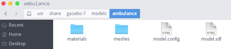
ambulance model文件夹:
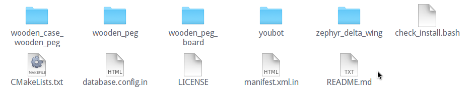
models文件夹内容:
Database (就相当于上面的models文件夹)
database.config : Meta data about the database. This is now populated automatically from CMakeLists.txt
textures and scripts subdirectories
The
database.configfile is only required for online repositories. A directory full of models on your local computer does not need adatabase.configfile.
database.config是发布到网上才需要,自己本地电脑上的models不需要这个文件
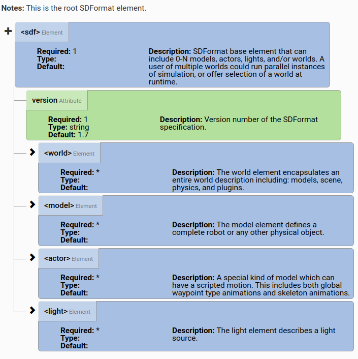
Each model must have a model.config file in the model‘s root directory that contains meta information about the model.
The format of this model.config is:
<?xml version="1.0"?>

<model>
  <name>My Model Name</name>
  <version>1.0</version>
  <sdf version=‘1.5‘>model.sdf</sdf>

  <author>
    <name>My name</name>
    <email>name@email.address</email>
  </author>

  <description>
    A description of the model
  </description>
</model>
The name of a SDF or URDF file that describes this model. The
versionattribute indicates what SDF version the file uses, and is not required for URDFs. Multiple <sdf> elements may be used in order to support multiple SDF versions.对于SDF,
<sdf></sdf>,URDF格式的文件不需要version属性,sdf文件如果要支持多个SDF版本,使用多个sdf标签,如:
model.sdf
model.sdf
model.sdf
<description>标签
- What the model is (e.g., robot, table, cup)
- What the plugins do (functionality of the model)
SDF Models refers to the <model> SDF tag, and is essentially a collection of links, joints, collision objects, visuals, and plugins.
Links: A link contains the physical properties of one body of the model. This can be a wheel, or a link in a joint chain. Each link may contain many collision and visual elements. Try to reduce the number of links in your models in order to improve performance and stability. For example, a table model could consist of 5 links (4 for the legs and 1 for the top) connected via joints. However, this is overly complex, especially since the joints will never move. Instead, create the table with 1 link and 5 collision elements.
记住一点:使用少link,即尽量将link变成其他一些link当中的collision和visual等元素来表述这些物体,而不是单独作为一个link来表述物体,这样稳定性和表现会更好
Collision: A collision element encapsulates(压缩;简述;概括) a geometry that is used for collision checking. This can be a simple shape (which is preferred), or a triangle mesh (which consumes greater resources). A link may contain many collision elements.
Visual: A visual element is used to visualize parts of a link. A link may contain 0 or more visual elements.
Inertial: The inertial(惯性的;不活泼的) element describes the dynamic properties of the link, such as mass and rotational inertia matrix.(转动惯量矩阵)
Sensor: A sensor collects data from the world for use in plugins. A link may contain 0 or more sensors.
Light: A light element describes a light source attached to a link. A link may contain 0 or more lights.
Joints: A joint connects two links. A parent and child relationship is established along with other parameters such as axis of rotation, and joint limits.
Plugins: A plugin is a shared library created by a third party to control a model.
获取meshes的方法:
Gazebo requires that mesh files be formatted as STL, Collada or OBJ, with Collada and OBJ being the preferred formats.
最好是格式化成Collada或者OBJ格式的
Tip: Use your 3D modeling software to move each mesh so that it is centered on the origin. This will make placement of the model in Gazebo significantly easier.
Tip: Collada and OBJ file formats allow you to attach materials to the meshes. Use this mechanism to improve the visual appearance of your meshes.
Tip: Keep meshes simple. This is especially true if you plan on using the mesh as a collision element. A common practice is to use a low polygon mesh for a collision element, and higher polygon mesh for the visual. An even better practice is to use one of the built-in shapes (box, sphere, cylinder) as the collision element.
最好使用Collada或者OBJ格式的,同时,需要碰撞检测的时候,最好选择内置的图形或者简单的低多边形作为碰撞元素。
http://gazebosim.org/tutorials?tut=build_model
gedit box.sdf
<?xml version=‘1.0‘?>
<sdf version="1.4">
  <model name="my_model">
    <pose>0 0 0.5 0 0 0</pose>
    <static>true</static>
    <link name="link">
      <inertial>
        <mass>1.0</mass>
        <inertia> <!-- inertias are tricky to compute -->
          <!-- http://gazebosim.org/tutorials?tut=inertia&cat=build_robot -->
          <ixx>0.083</ixx>       <!-- for a box: ixx = 0.083 * mass * (y*y + z*z) -->
          <ixy>0.0</ixy>         <!-- for a box: ixy = 0 -->
          <ixz>0.0</ixz>         <!-- for a box: ixz = 0 -->
          <iyy>0.083</iyy>       <!-- for a box: iyy = 0.083 * mass * (x*x + z*z) -->
          <iyz>0.0</iyz>         <!-- for a box: iyz = 0 -->
          <izz>0.083</izz>       <!-- for a box: izz = 0.083 * mass * (x*x + y*y) -->
        </inertia>
      </inertial>
      <collision name="collision">
        <geometry>
          <box>
            <size>1 1 1</size>
          </box>
        </geometry>
      </collision>
      <visual name="visual">
        <geometry>
          <box>
            <size>1 1 1</size>
          </box>
        </geometry>
      </visual>
    </link>
  </model>
</sdf>
Note that the origin of the Box-geometry is at the geometric center of the box, so in order to have the bottom of the box flush with the ground plane, an origin of
0 0 0.5 0 0 0is added to raise the box above the ground plane.x, y, z, a, b, c,设置的是这个点是这个盒子的几何中心的位置及姿态
Tip: The above example sets the simple box model to be static, which makes the model immovable. This feature is useful during model creation. Once you are done creating your model, set the
statictag to false if you want your model to be movable.先设置称static,方便模型创建,创建完成以后,再改为动态的,也就是将static标签设置为false:
<static>false</static>
设置model.sdf时,遵循一下顺序比较好:
也就是:LCVIJP
一般先把model.sdf、model.config先创建,然后逐渐增加组件,这样能够在gazebo里面直观看到设置是否正确,下面的移动机器人的例子就是这样。
http://gazebosim.org/tutorials?tut=build_robot&cat=build_robot
mkdir -p ~/.gazebo/models/my_robot
gedit ~/.gazebo/models/my_robot/model.config
<?xml version="1.0"?>
<model>
    <name>My Robot</name>
    <version>1.0</version>
    <sdf version=‘1.4‘>model.sdf</sdf>

    <author>
        <name>JacobLi</name>
        <email>2418454228@qq.com</email>
    </author>
    <description>
        My awesome robot.
    </description>
</model>
gedit ~/.gazebo/models/my_robot/model.sdf
<?xml version=‘1.0‘?>
<sdf version=‘1.4‘>
    <model name="my_robot">
    </model>
</sdf>
如上,在这里,我们就先创建了model.config和model.sdf文件,便于后面通过Gazebo显示我们所做的修改,后面就逐步添加对model.sdf的修改来完善模型
<?xml version=‘1.0‘?>
<sdf version=‘1.4‘>
    <model name="my_robot">
        <static>true</static>
        <link name=‘chassis‘>
            <pose>0 0 0.1 0 0 0</pose>

            <collision name=‘collision‘>
                <geometry>
                    <box>
                        <size>.4 .2 .1</size>
                    </box>
                </geometry>
            </collision>

            <visual name=‘visual‘>
                <geometry>
                    <box>
                        <size>.4 .2 .1</size>
                    </box>
                </geometry>
            </visual>
        </link>
    </model>
</sdf>
<static>true</static>
make our model static, which means it will be ignored by the physics engine. As a result the model will stay in one place and allow us to properly align all the components.
设置为静态便于对齐其他组件
<link name=‘chassis‘>
  <pose>0 0 0.1 0 0 0</pose>

  <collision name=‘collision‘>
    <geometry>
      <box>
        <size>.4 .2 .1</size>
      </box>
    </geometry>
  </collision>

  <visual name=‘visual‘>
    <geometry>
      <box>
        <size>.4 .2 .1</size>
      </box>
    </geometry>
  </visual>
</link>
link下这里先包含三个元素,分别是pose,collision,visual
pose元素指明了盒子的几何中心的位置及姿态,对应为x, y, z, a, b, c (三个轴以及绕三个轴的旋转角),
碰撞元素指定碰撞检测引擎使用的形状。 视觉元素指定渲染引擎使用的形状
created a
boxwith a size of0.4 x 0.2 x 0.1meters,The
collisionelement specifies the shape used by the collision detection engine.The
visualelement specifies the shape used by the rendering engine.For most use cases the
collisionandvisualelements are the same.The most common use for different
collisionandvisualelements is to have a simplifiedcollisionelement paired with avisualelement that uses a complex mesh. This will help improve performance.
设置碰撞以及可视化的盒子的大小为同样,多数情况下collision和visual的设置相同
通常设置collision和visual不同的情况为collision元素只进行简单设置,而visual元素使用复杂的网格进行设置(即碰撞要简单,可视化要优化设置)
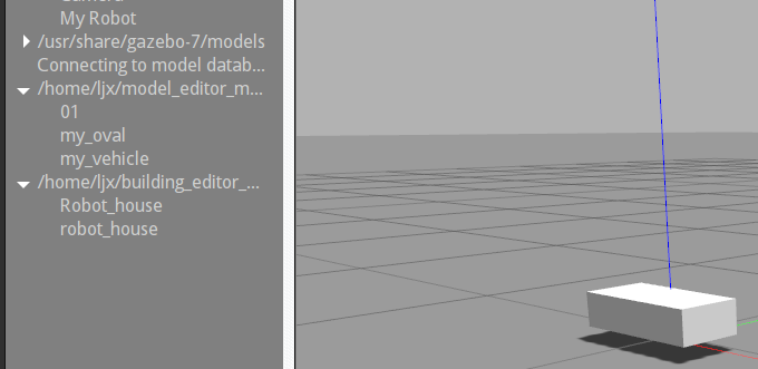
下面直接进入到gazebo里面,使用insert,插入自己创建的model(单击My Robot)
在chassis的visual元素后面加入如下
<collision name=‘caster_collision‘>
   <pose>-0.15 0 -0.05 0 0 0</pose>
   <geometry>
     <sphere>
       <radius>.05</radius>
     </sphere>
   </geometry>

   <surface>
     <friction>
       <ode>
         <mu>0</mu>
         <mu2>0</mu2>
         <slip1>1.0</slip1>
         <slip2>1.0</slip2>
       </ode>
     </friction>
   </surface>
</collision>

<visual name=‘caster_visual‘>
  <pose>-0.15 0 -0.05 0 0 0</pose>
  <geometry>
    <sphere>
      <radius>.05</radius>
    </sphere>
  </geometry>
</visual>
就是脚轮caster的collision和visual元素
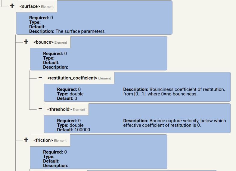
这里的collision元素中的surface元素的写法参见:
http://gazebosim.org/tutorials?tut=friction
http://sdformat.org/spec?ver=1.5&elem=collision#surface_friction
ODE (Open Dynamic Engine) 是一个免费的具有工业品质的刚体动力学的库,一款优秀的开源物理引擎,它为主程序员Russell Smith和几位开源社区贡献者共同努力下开发的。它能很好地仿真现实环境中的可移动物体,它是快速,强健和 可移植的。而且它有内建的碰撞检测系统
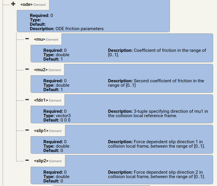
When two object collide, such as a ball rolling on a plane, a friction term is generated. In ODE this is composed of two parts, ‘‘‘mu‘‘‘ and ‘‘‘mu2‘‘‘, where:
- ‘‘‘mu‘‘‘ is the Coulomb friction coefficient for the first friction direction, and
- ‘‘‘mu2‘‘‘ is the friction coefficient for the second friction direction (perpendicular to the first friction direction).
ODE包含两个由两个部分组成:μ和μ2
‘‘mu‘‘是第一个摩擦方向的库仑摩擦系数,
“ mu2”是第二摩擦方向(垂直于第一摩擦方向)的摩擦系数。
ODE will automatically compute the first and second friction directions for us.
The two objects in collision each specify ‘‘‘mu‘‘‘ and ‘‘‘mu2‘‘‘. Gazebo will choose the smallest ‘‘‘mu‘‘‘ and ‘‘‘mu2‘‘‘ from the two colliding objects.
当两个物体碰撞的时候,Gazebo会自动选择两个碰撞的物体中选择μ的最小值和μ2的最小者
The valid range of values for ‘‘‘mu‘‘‘ and ‘‘‘mu2‘‘‘ is any non-negative number, where 0 equates to a friction-less contact and a large value approximates a surface with infinite friction.
0是摩擦最小为无摩擦,摩擦系数越大,摩擦越大
具体摩擦系数参考:online references
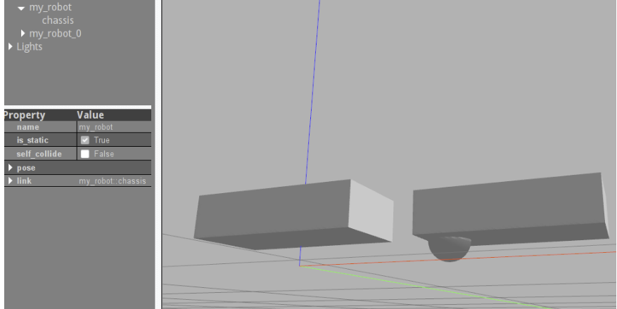
后面直接重新insert一个,直接拖动就直接加载出新设置的模型(可以直接删除第一个模型)
       <link name="left_wheel">
           <pose>0.1 0.13 0.1 0 1.5707 1.5707</pose>
           <collision name="collision">
               <geometry>
                   <cylinder>
                       <radius>.1</radius>
                       <length>.05</length>
                   </cylinder>
               </geometry>
           </collision>
           <visual name="visual">
               <geometry>
                   <cylinder>
                       <radius>.1</radius>
                       <length>.05</length>
                   </cylinder>
               </geometry>
           </visual>
       </link>
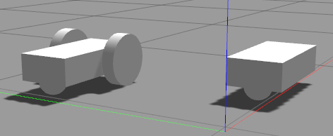
这里将左轮单独作为一个link出来,右轮同理,只是pose变了(如上的三条线中,红线为x,绿线为y,蓝线为z,右手螺旋,左右轮对应的只是y坐标相反)。
        <link name="right_wheel">
            <pose>0.1 -0.13 0.1 0 1.5707 1.5707</pose>
            <collision name="collision">
                <geometry>
                    <cylinder>
                        <radius>.1</radius>
                        <length>.05</length>
                    </cylinder>
                </geometry>
            </collision>
            <visual name="visual">
                <geometry>
                    <cylinder>
                        <radius>.1</radius>
                        <length>.05</length>
                    </cylinder>
                </geometry>
            </visual>
        </link>
修改为<statif>false</static>,添加如下代码(于link元素同级)
        <joint type="revolute" name="left_wheel_hinge">
            <pose>0 0 -0.03 0 0 0</pose>
            <child>left_wheel</child>
            <parent>chassis</parent>
            <axis>
                <xyz>0 1 0</xyz>
            </axis>
        </joint>

        <joint type="revolute" name="right_wheel_hinge">
            <pose>0 0 0.03 0 0 0</pose>
            <child>right_wheel</child>
            <parent>chassis</parent>
            <axis>
                <xyz>0 1 0</xyz>
            </axis>
        </joint>
两个轮绕y轴进行旋转,都连接到底盘上
end
官网给出如下想法可以自己进行尝试实现
Idea: A quadruped that consists of torso with four cylindrical legs. Each leg is attached to the torso with a revolute joint.
四足一躯干的动物
Idea: A six wheeled vehicle with a scoop front loading mechanism.
带有前铲式装载机构的六轮车
标签:bottom 插入 type 最好 gre must direction eve cte
原文地址:https://www.cnblogs.com/BoltLi/p/12584184.html