标签:模块 sha var verilog mda tput 放大 param ilog
@(verilog)
乐鑫2020笔试题:
描述:模块输入口是并行的2bit,实现对\((1011001)_2\)的序列检测,输入数据顺序为高位2bit先输入,当检测到序列时输出一拍高电平脉冲,用verilg描述。
采用状态机描述,先列出状态转移表,跟单bit输入不同的是,这里的输入是并行的2bit:
| state\input | 00 | 01 | 10 | 11 |
|---|---|---|---|---|
| 0 | 0 | 1 | 10 | 1 |
| 1 | 0 | 101 | 10 | 1 |
| 10 | 0 | 1 | 10 | 1011 |
| 101 | 0 | 101 | 10110 | 1 |
| 1011 | 101100 | 101 | 10 | 1 |
| 10110 | 0 | 1011001 | 10 | 1011 |
| 101100 | 0 | 1 | 10 | 1 |
| 0 | 101 | 10 | 1 |
以及输出的状态转移表:
| state\input | 00 | 01 | 10 | 11 |
|---|---|---|---|---|
| 0 | 0 | 0 | 0 | 0 |
| 1 | 0 | 0 | 0 | 0 |
| 10 | 0 | 0 | 0 | 0 |
| 101 | 0 | 0 | 0 | 0 |
| 1011 | 0 | 0 | 0 | 0 |
| 10110 | 0 | 1 | 0 | 0 |
| 101100 | 0 | 0 | 1 | 1 |
| 0 | 0 | 0 | 0 |
通过分析可以发现,1011001和1状态是完全等价的,因此可以归并,并且其他状态的转移也有相同的,也可以放到一起:
状态转移表:
| state\input | 00 | 01 | 10 | 11 |
|---|---|---|---|---|
| 0\101100 | 0 | 1 | 10 | 1 |
| 1 | 0 | 101 | 10 | 1 |
| 10\10110 | 0 | 1 | 10 | 1011 |
| 101 | 0 | 101 | 10110 | 1 |
| 1011 | 101100 | 101 | 10 | 1 |
输出转移表:
| state\input | 00 | 01 | 10 | 11 |
|---|---|---|---|---|
| 0\1\10\101\1011 | 0 | 0 | 0 | 0 |
| 10110 | 0 | 1 | 0 | 0 |
| 101100 | 0 | 0 | 1 | 1 |
Verilog代码:
`timescale 1ns/1ps

module two_bit_input_seq_detector
(
input                                   clk,
input                                   rst_n,
input        [1:0]                      data,
output reg                              success
);

reg [2:0] current_state;
reg [2:0] next_state;

parameter S0      =  3‘b000,
          S1      =  3‘b001,
          S10     =  3‘b011,
          S101    =  3‘b010,
          S1011   =  3‘b110,
          S10110  =  3‘b111,
          S101100 =  3‘b101;

always @(posedge clk or negedge rst_n) begin
    if(!rst_n) current_state <= 3‘b0;
    else current_state <= next_state;
  end

always @(*)
  case(current_state)
    S0,S101100:
            case(data)
              2‘b00: next_state = S0;
              2‘b01: next_state = S1;
              2‘b10: next_state = S10;
              2‘b11: next_state = S1;
            endcase
    S1:     case(data)
              2‘b00: next_state = S0;
              2‘b01: next_state = S101;
              2‘b10: next_state = S10;
              2‘b11: next_state = S1;
            endcase
    S10,S10110:
            case(data)
              2‘b00: next_state = S0;
              2‘b01: next_state = S1;
              2‘b10: next_state = S10;
              2‘b11: next_state = S1011;
            endcase
    S101:   case(data)
              2‘b00: next_state = S0;
              2‘b01: next_state = S101;
              2‘b10: next_state = S10110;
              2‘b11: next_state = S1;
            endcase
    S1011:  case(data)
              2‘b00: next_state = S101100;
              2‘b01: next_state = S101;
              2‘b10: next_state = S10;
              2‘b11: next_state = S1;
            endcase
    default:         next_state = S0;
  endcase


always @(posedge clk or negedge rst_n) begin
    if(!rst_n) begin
      success <= 0;
    end else begin
      case(current_state)
        S0,S1,S10,S101,S1011:        success <= 0;
        S10110 : if(data == 2‘b01)   success <= 1;
                 else                success <= 0;
        S101100: if(data[1] == 1‘b1) success <= 1;
                 else                success <= 0;
        default:                     success <= 0;
      endcase
    end
  end

endmodule
testbench:
`timescale 1ns/1ps

module two_bit_input_seq_detector_tb();


reg         clk;
reg         rst_n;
reg   [1:0] data;

wire     success;
reg [127:0] seq;


always #1 clk = ~clk;
initial begin
  clk = 0;
  data = 0;
  rst_n = 1;
  #4 rst_n = 0; #2 rst_n = 1;

  seq = 0;
  while(1) begin
    @(posedge clk) begin
      data <= $random%4;
      seq <= (seq<<2) + data;
    end
  end

end


two_bit_input_seq_detector U_2BIT_INPUT_SEQ_DETECTOR_0
(  .clk     ( clk     ),
   .rst_n   ( rst_n   ),
   .data    ( data    ),
   .success ( success ));


initial begin
  $fsdbDumpvars();
  $fsdbDumpMDA();
  $dumpvars();
  #1000 $finish;
end

endmodule
波形图:

放大来看:

可以看到,功能正确。
使用移位寄存器解决序列检测问题是真的简单粗暴,直接上代码:
`timescale 1ns/1ps

module two_bit_input_seq_detector_v2
(
input                                   clk,
input                                   rst_n,
input        [1:0]                      data,
output                                  success
);

parameter DETECTOR = 7‘b1011001;
reg [7:0] fifo;

always @(posedge clk or negedge rst_n) begin
    if(!rst_n) begin
      fifo <= 8‘b0;
    end else begin
      fifo <= {fifo[5:0],data};
    end
end

assign success = (fifo[7:1]==DETECTOR || fifo[6:0]==DETECTOR) ? 1:0;

endmodule
testbench:
`timescale 1ns/1ps

module two_bit_input_seq_detector_v2_tb();


reg         clk;
reg         rst_n;
reg   [1:0] data;

wire     success;
reg [127:0] seq;


always #1 clk = ~clk;
initial begin
  clk = 0;
  data = 0;
  rst_n = 1;
  #4 rst_n = 0; #2 rst_n = 1;

  seq = 0;
  while(1) begin
    @(posedge clk) begin
      data <= $random%4;
      seq <= (seq<<2) + data;
    end
  end

end


two_bit_input_seq_detector_v2 U_TWO_BIT_INPUT_SEQ_DETECTOR_V2_0
(  .clk     ( clk     ),
   .rst_n   ( rst_n   ),
   .data    ( data    ),
   .success ( success ));


initial begin
  $fsdbDumpvars();
  $fsdbDumpMDA();
  $dumpvars();
  #1000 $finish;
end

endmodule
仿真波形:
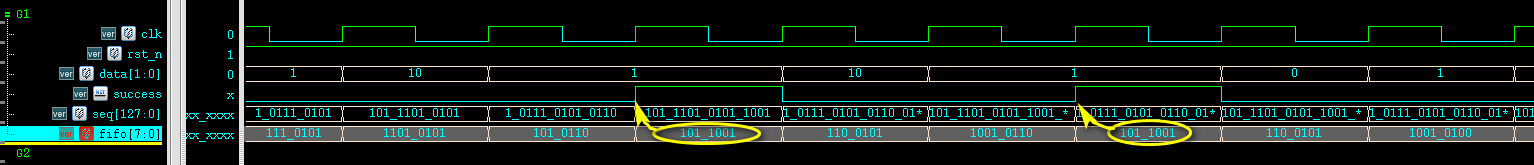
功能正确!
标签:模块 sha var verilog mda tput 放大 param ilog
原文地址:https://www.cnblogs.com/lyc-seu/p/13030250.html