本文研究NodeMCU的GPIO的用法,主要是IO的电压范围和电流范围
https://github.com/nodemcu/nodemcu-firmware/wiki/nodemcu_api_en
|
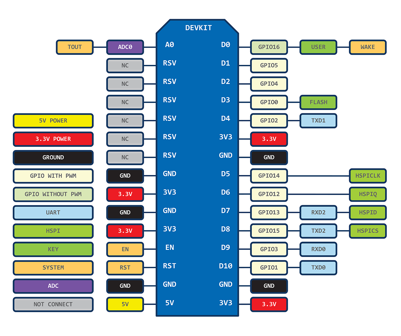
IO index |
ESP8266 pin |
IO index |
ESP8266 pin |
|---|---|---|---|
|
0 [*] |
GPIO16 |
7 |
GPIO13 |
|
1 |
GPIO4 |
8 |
GPIO15 |
|
2 |
GPIO5 |
9 |
GPIO3 |
|
3 |
GPIO0 |
10 |
GPIO1 |
|
4 |
GPIO2 |
11 |
GPIO9 |
|
5 |
GPIO14 |
12 |
GPIO10 |
|
6 |
GPIO12 |
** D0(GPIO16) can only be used asgpio read/write. no interrupt supported. no pwm/i2c/ow supported. *
NodeMCU的API
https://github.com/nodemcu/nodemcu-firmware/wiki/nodemcu_api_en
gpio.OUTPUT, gpio.INPUT, gpio.INT, gpio.HIGH, gpio.LOW
initialize pin to GPIO mode, set the pin in/out mode, internalpullup.
gpio.mode(pin, mode, pullup)
pin: 0~12, IO index
mode: gpio.OUTPUT or gpio.INPUT, orgpio.INT(interrupt mode) pullup: gpio.PULLUP or gpio.FLOAT, default:gpio.FLOAT.
nil
    -- set gpio 0 as output.
    gpio.mode(0, gpio.OUTPUT)
read pin value.
gpio.read(pin)
pin: 0~12, IO index
number:0 - low, 1 - high
    -- read value of gpio 0.
    gpio.read(0)
set pin value.
gpio.write(pin)
pin: 0~12, IO index
level: gpio.HIGH or gpio.LOW
nil
    -- set pin index 1 to GPIO mode, and set the pin to high.
    pin=1
    gpio.mode(pin, gpio.OUTPUT)
    gpio.write(pin, gpio.HIGH)
set the interrupt callback function for pin.
gpio.trig(pin, type, function(level))
pin: 1~12, IO index, pin D0 does not supportInterrupt.
type: "up", "down", "both","low", "high", which represent rising edge,falling edge, both edge, low level, high level trig modeseparately.
function(level): callback function when triggered. Thegpio level is the param. Use previous callback function if undefinedhere.
nil
    -- use pin 0 as the input pulse width counter
    pulse1 = 0
    du = 0
    gpio.mode(1,gpio.INT)
    function pin1cb(level)
     du = tmr.now() – pulse1
     print(du)
     pulse1 = tmr.now()
     if level == 1 then gpio.trig(1, "down") else gpio.trig(1, "up") end
    end
    gpio.trig(1, "down",pin1cb)
https://nurdspace.nl/ESP8266#Power_Management
A total of up to 16 GPIO pins. The firmware can assign themdifferent functions. Each GPIO can be configured internal pullup /pulldown resistors available software registers sampled input,triggering edge or level CPU interrupt input, trigger level wake-upinterrupt input, open-drain or complementary push-pull outputdrivers, software register output source or sigma-delta PWM DAC.These pins are multiplexed with other functions, such as the maininterface, UART, SI, Bluetooth co-existence and so on.
Digital IO pad is two-way, three states. It includes a three-statecontrol input and output buffers. In addition, for low-poweroperation, IO can be set to hold state. For example, when we reducethe chip‘s power consumption, all the output enable signal can be setto maintain a low-power state. Hold function can be selectivelyimplanted IO in need. When the IO help internal and external circuitdriving, hold function can be used to hold last state. Hold functionto pin introduce some positive feedback. Therefore, the externaldrive pin must be stronger than the positive feedback. However, therequired driving force size is still small, in the 5uA of.
|
Variables |
Symbol |
Min |
Max |
Units |
|---|---|---|---|---|
|
Input Low Voltage |
Vil |
-0.3 |
0.25xV10 |
V |
|
Input High Voltage |
Vih |
0.75xV10 |
3.6 |
V |
|
Input leakage current |
IIL |
- |
50 |
nA |
|
Output Low Voltage |
VOL |
- |
0.1xV10 |
V |
|
Output High Voltage |
VOH |
0.8xV10 |
- |
V |
|
Input pin capacitance |
Cpad |
- |
2 |
pF |
|
VDDIO |
V10 |
1.7 |
3.6 |
V |
|
Current |
Imax |
- |
12 |
mA |
|
Temperature |
Tamb |
-20 |
100 |
C |
All digital IO pins must add an overvoltage protection circuit(snap back circuit) between the pin and ground. Usually bounce (snapback) voltage is about 6V, while maintaining the voltage is 5.8V.This prevents excessive voltage and generating ESD. Diodes also avoidreverse voltage output devices.
原文地址:http://blog.csdn.net/coolwaterld/article/details/45367109