标签:style blog http strong 文件 数据
在前面阅读理解了I2C的官方协议文档后,就拿s3c2440和EEPROM来验证一下.
本来是想用s3c2440的SDA和SCL管脚复用为GPIO来模拟的,但在没有示波器的情况下搞了一周,怎么都出不来,最后还是放弃了.甚至参考了linux下i2c-algo-bit.c和i2c-gpio.c,依然没调出来.如果有示波器,可能很快就能找到原因,现在完全不知道问题出在哪里.其实想用GPIO模拟I2C的目的很简单,以一种简单而又深刻的方式来理解I2C.
既然这条路暂时没法走,退而求其次,用s3c2440的I2C接口来访问EEPROM,只要按照datasheet的来做,基本上不用考虑时序咯.
从s3c2440和AT24C02A的datasheet开始:
s3c2440的介绍其实很简单,IIC-bus接口有四种操作模式:
Master transmitter mode Master receive mode Slave transmitter mode Slave receive mode
但实际上,我们只会用到M-Tx和M-Rx,因为在s3c2440和EEPROM的连接中,没办法将s3c2440当作slave.
然后s3c2440的datasheet从I2C的协议文档上copy了一些内容:开始终止条件\数据传输格式\ACK\读写操作\总线仲裁\终止条件等.这些还是看I2C的协议文档比较好.
I2C-BUS的配置:
为了控制SCL的频率,IICCON中可以控制一个4bit的分频器.IICADD寄存器用来保存IIC-Bus的接口地址,这个实际也无需用,只有访问从设备时才需要地址.而这里s3c2440是主设备.
在每次IIC Tx/Rx操作前,都要做下面的操作:
如果需要的话,写从地址到IICADD
设置IICCON寄存器(使能中断,定义SCL的周期)
设置IICSTAT来使能串行输出
然后就是M-Tx和M-Rx操作模式的流程图,后面的代码就是严格按照这个图来的.这里就不截图了.
寄存器的说明大概如下:
#define rIICCON (*(volatile unsigned *)0x54000000) /********************** [7]:ack enable bit [6]:Tx clock source selection 0:IICCLK = PCLK/16 1:IICCLK = PCLK/512 [5]:Tx/Rx interrupt [4]:interrupt pending flag !!!! [3:0]:Tx clock = IICCLK/(IICCON[3:0]+1) **********************/ #define rIICSTAT (*(volatile unsigned *)0x54000004) /********** [7:6]:10:M-Rx 11:M-Tx [5]:busy signal status/start stop conditon !!! [4]:serial output enable/disable bit 1:enable [3]:iic arbitration procedure status flag bit || which didn‘t used [2]:address-as-slave status flag !!! [1]:address zero status flag [0]:last-received bit status flag 0:ack 1:nack **********/ #define rIICADD (*(volatile unsigned *)0x54000008) /********* * [7:1]:slave address 只有在IICSTAT的output disable时,IICADD才可以写.随时可以读. * ************/ #define rIICDS (*(volatile unsigned *)0x5400000c) /************** * [7:0]:8bit data shift reg for IIC-Bus Tx/Rx operation.只有IICSTAT的output enable时,IICDS才可以写.随时可以读. * *************/ #define rIICLC (*(volatile unsigned *)0x54000010) /************** * 该寄存器用于多主机的情况,暂时用不到 * ************/
下面看下AT24C02A的datasheet:
AT24C02A:2K的容量,32pages,每个page8个字节,总共256字节.读写需要8bit的word address.
AT24C02A的地址是从下图来的:
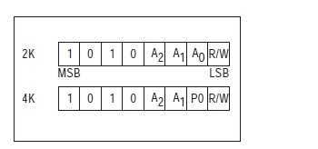
所以地址就是我们看到的0xa0,A2 A1 A0因为在原理图上这三个管脚都接的低电平.
写操作:
以字节写的图为例:
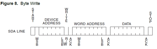
结合s3c2440的M-Tx模式,代码操作如下:
void I_Write(unsigned int slvaddr, unsigned char addr, unsigned char data)
{
	unsigned int ack;
	init(slvaddr);
	//rIICSTAT |= 0x3<<6;  //configure M Tx mode
	rIICDS = slvaddr;//0xa0;  //write slave address to IICDS
	rIICCON&=~0x10; //clear pending bit
	rIICSTAT = 0xf0;  //(M/T start)

	//the data of the IICDS is transmitted
	uart_SendByte(‘a‘);
	while((rIICCON & 1<<4) == 0);//udelay(10);//ack period and then interrupt is pending

	if((rIICSTAT & 0x01)==0)
		uart_SendByte(‘y‘);//ack = 0;    //收到应答
	else
		uart_SendByte(‘n‘);//ack = 1;    //没有应答
	rIICDS = addr;
	rIICCON&=~0x10; //clear pending bit
	//the data of the IICDS is shifted to sda
	uart_SendByte(‘b‘);
	while((rIICCON & 1<<4) == 0);//udelay(10);//ack period and then interrupt is pending
	if((rIICSTAT & 0x01)==0)
		uart_SendByte(‘y‘);//ack = 0;    //收到应答
	else
		uart_SendByte(‘n‘);//ack = 1;    //没有应答
	rIICDS = data;
	rIICCON&=~0x10; //clear pending bit
	//the data of the IICDS is shifted to sda
	uart_SendByte(‘c‘);
	while((rIICCON & 1<<4) == 0);//udelay(10);//ack period and then interrupt is pending
	if((rIICSTAT & 0x01)==0)
		uart_SendByte(‘y‘);//ack = 0;    //收到应答
	else
		uart_SendByte(‘n‘);//ack = 1;    //没有应答
	rIICSTAT = 0xD0; //write (M/T stop to IICSTAT)
	//rIICCON = 0xe0;
	rIICCON&=~0x10; //clear pending bit
	uart_SendByte(‘d‘);
	while((rIICSTAT & 1<<5) == 1);

}
读操作:
以随机读的图为例:
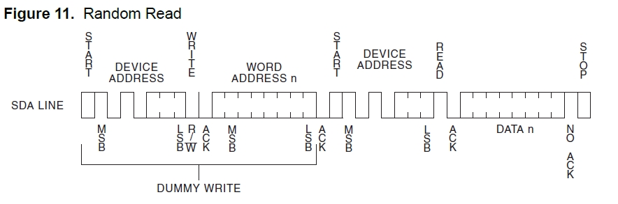
随机读要复杂点,因为前面的DUMMY WRITE要用M-Tx模式,而后面真正的读操作要用M-Rx模式.结合s3c2440的模式操作的流程图,代码如下:
unsigned char I_Read(unsigned int slvaddr, unsigned char addr)
{
	unsigned char data;
	int ack;
	init(slvaddr);
	//rIICSTAT |= 0x3<<6;  //configure M Tx mode

	rIICDS = slvaddr;//0xa0;  //write slave address to IICDS
	rIICCON&=~0x10; //clear pending bit
	rIICSTAT = 0xf0;  //(M/T start)
	//the data of the IICDS is transmitted
	while((rIICCON & 1<<4) == 0);//udelay(10);//ack period and then interrupt is pending
	if((rIICSTAT & 0x01)==0)
		uart_SendByte(‘y‘);//ack = 0;    //收到应答
	else
		uart_SendByte(‘n‘);//ack = 1;    //没有应答

	rIICDS = addr;
	rIICCON&=~0x10; //clear pending bit
	//the data of the IICDS is shifted to sda
	while((rIICCON & 1<<4) == 0);//udelay(10);//ack period and then interrupt is pending
	if((rIICSTAT & 0x01)==0)
		uart_SendByte(‘y‘);//ack = 0;    //收到应答
	else
		uart_SendByte(‘n‘);//ack = 1;    //没有应答


	init(slvaddr);
	rIICSTAT &= ~(0x1<<6);//configure M Rx mode
	rIICSTAT |= 0x1<<7;
	//rIICSTAT |= 0x2<<6;  //configure M Rx mode
	rIICDS = slvaddr;
	rIICCON&=~0x10; //clear pending bit
	rIICSTAT = 0xb0;  //(M/R Start)
	//the data of IICDS(slave address) is transmitted
	while((rIICCON & 1<<4) == 0);//udelay(10);//uart_SendByte(‘o‘);//ack period and then interrupt is pending::
	if((rIICSTAT & 0x01)==0)
		uart_SendByte(‘y‘);//ack = 0;    //收到应答
	else
		uart_SendByte(‘n‘);//ack = 1;    //没有应答

	data = rIICDS;
	if(data==160)
		uart_SendByte(‘o‘);
	rIICCON&=~0x10; //clear pending bit
	//sda is shifted to IICDS
	while((rIICCON & 1<<4) == 0);//udelay(10);//ack period and then interrupt is pending
	if((rIICSTAT & 0x01)==0)
		uart_SendByte(‘y‘);//ack = 0;    //收到应答
	else
		uart_SendByte(‘n‘);//ack = 1;    //没有应答
	uart_SendByte(‘a‘);
	rIICSTAT = 0x90;
	uart_SendByte(‘b‘);
	rIICCON&=~0x10; //clear pending bit
	uart_SendByte(‘c‘);
	while((rIICSTAT & 1<<5) == 1)uart_SendByte(‘o‘);
	uart_SendByte(‘d‘);
	return data;

}
这个EEPROM的其他读写操作依此类推.
最后,做一下总结:
1.单次的写字节和随机读之间应该加延时,验证过程中发现,在两次写字节之间延时100us的话,在第二次写字节的时候就收不到ACK.将延时改为1000us就正常了.
2.IICDS的读写操作一定要在清楚IIC interrupt pending bit之前做,也就是代码中出现的:
	rIICDS = slvaddr;
	rIICCON&=~0x10; //clear pending bit
while((rIICCON & 1<<4) == 0);//udelay(10);//ack period and then interrupt is pending if((rIICSTAT & 0x01)==0) uart_SendByte(‘y‘);//ack = 0; //收到应答 else uart_SendByte(‘n‘);//ack = 1; //没有应答
只需要上面的代码就可以了,通过轮询IICCON的第4bit来查看ack period and then interrupt is pending.
当然如果用中断系统中IIC中断也是可以的,一个是中断方式,一个是轮询方式,在这里感觉差别不大.
关于I2C裸机到此为止,但是gpio模拟I2c一直耿耿于怀啊~~
在工作中,linux下做过用I2C子系统用GPIO模拟I2C.那个只要配置好GPIO的input和output,构造数据结构,驱动就能工作了,不得不佩服这个子系统的强大.因为前面的blog对文件系统和设备模型都做过分析,但并没有针对特定的子系统做过分析,过段时间就来分析linux的I2C,学习C语言也是如何实现OOP的某些特性的,体会好代码的设计思路.
(6)s3c2440用I2C接口访问EEPROM,布布扣,bubuko.com
标签:style blog http strong 文件 数据
原文地址:http://www.cnblogs.com/0822vaj/p/3815785.html