标签:des style blog http color 2014
[0001] The present invention relates to communications and, more particularly, to systems and methods for exchanging small network management protocol (SNMP) messages in large complex networks.
[0002] Managing and monitoring connected devices in a network is important for network administrators in local area network applications and other much larger more complex networks. Network management systems are utilized to monitor, interpret and control the operation of a network. Typically, the network management system includes agents that reside on network devices that monitor and accumulate operational data and detect exceptional events. A manager is provided at a network management station that can request operational data and/or receive event notifications from one or more network devices via the network device agents. The manager can be equipped to interpret the operational data and/or received event notifications from the agents. Additionally, the manager can be equipped to effect control of network operations by transmitting command requests to the agents, which then execute the command requests.
[0003] Several protocols have been developed to enable management and monitoring of devices connected to a network. These protocols often include objects and procedures for accessing information associated with a network attached device. The Simple Network Management Protocol (SNMP) is an example of a relatively well known protocol for managing and monitoring network devices. The SNMP protocol uses User Datagram Protocol (UDP) packets to send and receive the information sent back and forth between management software and SNMP agents. SNMP was developed to provide a tool for multi-vendor, interoperable network management. SNMP includes a set of standards for network management including a protocol, database structure specification and a set of data objects. Network administrators can address queries and commands to network nodes and devices. SNMP monitors network performance and status, controls operational parameters and reports, analyzes and isolates faults. The protocol does these functions by transporting management information between "Managers" and "Agents".
[0004] SNMP defines three basic components, an agent, a manager and a Management Information Base (MIB). An agent is a component that resides within a managed network device such as a host, gateway, or terminal server. Each agents stores management data and respond to management request for data. An agent can also send an unsolicited SNMP message referred to as a "TRAP" to a manager after sensing a predefined condition. A manager is a component that resides in a network management station. The manager provides an administrator with the functionality to transmit query and control commands to an agent. A MIB is a managed object database, accessible to agents and manipulated via SNMP for network management application. For example, the MIB may specify data variables which track statistics on the status of network traffic, incoming and outgoing data and failures (e.g., routing failures).
[0005] SNMP specifies five types of commands or verbs called Protocol Data Units (PDUs): GetRequest, GetNextRequest, SetRequest, GetResponse and Trap. Agents retrieve management data after receiving a GetRequest or a GetNextRequest. Manager use GetNextRequest to retrieve single values of the managed objects. The GetNextRequest is issued by the manager to begin a primitive block transfer and the agent returns the selected data with a GetResponse verb. Managers use SetRequest commands for instructing agents to alter MIB variables, while "TRAPS" are unsolicited messages sent by agents to managers after sensing predefined conditions. The second version of SNMP introduced two additional operations: Inform and GetBulk. Inform allows one manager to send trap type information to another manager and request a response. GetBulk allows a manager to retrieve efficiently large blocks of data, such as multiple rows in a table, which would otherwise require the transmission of many small blocks of data.
[0006] SNMP was originally designed for network management of single networks. However, recently the need and ability to interconnect networks has evolved. New technologies have emerged to make it possible to interconnect many disparate physical networks and make them function as a single coordinated unit. Internetworking makes is possible for a host to communicate with hosts on different networks. The size of an internet or group of interconnected networks can be quite large and complex making network management more complex. Some tools such as SNMP have not been designed to operate in such large networks. For example, devices on networks can include similar Internet Protocol (IP) addresses. When the networks are connected to one another, the IP addresses are duplicated. SNMP has no mechanism to differentiate between devices with similar IP addresses amongst different interconnected networks. Conventionally, a network administrator would have to reconfigure devices on the network to eliminate duplicate IP addresses prior to utilizing SNMP as a network management tool for large complex interconnected networks.
[0025] The present invention relates to systems and methods for exchanging SNMP messages between devices residing across a plurality of different networks joined together by a common network backbone. The system and methods utilize network identification information to transmit the SNMP messages to a destination device residing in a network. Providing network identification information in the SNMP messages allows devices in different networks to have similar IP addresses, while still allowing SNMP tools to facilitate network managements when networks are coupled to one another to form a larger more complex network (e.g., internet). Therefore, devices of previously configured networks do not have to be reconfigured manually to alleviate the problem of duplicate IP addresses when the networks are joined together.
[0026]?FIG. 1?illustrates a system?10?comprising a plurality of networks joined to one another by a common network backbone?14. The network backbone?14?can be a hardwired data communication path made of twisted pair cable, shielded coaxial cable or fiber optic cable, for example, or may be wireless or partially wireless in nature. A network management station?12?is provided coupled to the network backbone?14. The network management station?12?allows a system administrator to transmit and receive MIB variables of SNMP agents residing on different networks via SNMP PDUs. The network management station?12?transmits and receives SNMP packets or messages to and from a particular device at a particular network. The network management station?12?translates the IP address of the device in the SNMP packet so that it is also provided with network identification information. For example, the network management station?12?can translate the IP address of the device by adding a network identifier to the SNMP packet. Alternatively, the network management station?12?can translate the IP address of the device into a virtual address to be transmitted over the backbone?14.
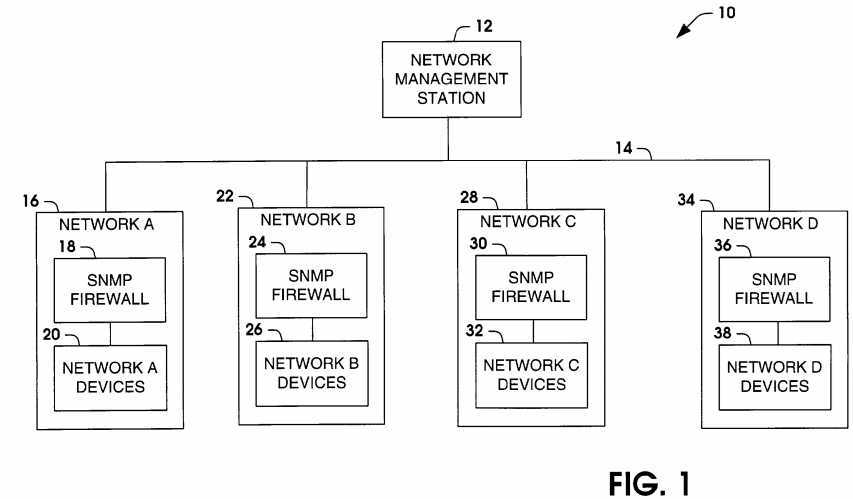
[0027] A destination network is provided with an SNMP firewall that filters out the modified SNMP packets to determine if the packet is destined for the respective network. If the SNMP packet is destined for the respective network, the SNMP firewall translates the modified SNMP packet address back to the original IP address and forwards the SNMP packet to the destination device. The destination device then transmits a response in a conventional manner. The SNMP firewall then retranslates the address residing in the response from the destination device and transmits the response back over the network backbone?14?to the network management station?12. Additionally, event information such as that occurring in a "TRAP" PDU defined at the device will have network identifier information incorporated into the SNMP packet by the SNMP firewall prior to transmission to the network management station?12. Therefore, devices with similar IP addresses can reside in the system without being modified by the system administrator since the network management station?12?and the SNMP firewalls cooperate to resolve the appropriate destination for transmission and reception of SNMP management messages.
[0028] In the example of?FIG. 1, a?first network?16, labeled network A, includes an SNMP firewall?18?and a plurality of network devices?20. A second network?22, labeled network B, includes an SNMP firewall?24?and a plurality of network devices?26. A third network?28, labeled network C, includes an SNMP firewall?30?and a plurality of network devices?32, and a fourth network?34, labeled network D, includes an SNMP firewall?36?and a plurality of network devices?38. SNMP messages pass between the network management station?12?and a destination device residing on a respective network through a respective network SNMP firewall. The SNMP firewall translates the address in the SNMP messages to include or remove network identifier information, so that messages are received by the appropriate destination device regardless if devices in different networks have similar IP addresses.
[0029] For example, a network administrator may wish to execute the following command to a machine on network B: $ snmpget 192.168.0.2 public.1.3.6.1.2.1.1.6.0. However, a device in network A and a device in network C may have the same IP address. Therefore, there is not guarantee that the command will reach the proper machine. In accordance with an aspect of the present invention, an administrator issues a similar command such as: $ snmpget B192.168.0.2 public.1.3.6.1.2.1.1.6.0. where B identifies the particular network hosting the destination device. The network management station?12?would then insert the network identifier information in the messages passed from the network management station?12?over the network backbone. The destination network SNMP firewall?24?would then determine if the SNMP message included a network or community identifier for that network, and forward the SNMP message to the desired destination device?26. A similar approach is followed for responses from the devices regarding event information transmitted to the network management station?12.
[0030] It is to be appreciated that each network in an multi-network system (e.g., internet) can be provided with a corresponding SNMP network management station that performs the functions associated with network management, such as that performed by an SNMP manager. Additionally, the SNMP network management station can include functionality associated with providing network community information to SNMP messages.?FIG. 2illustrates a first network?52, labeled network E, coupled to the Internet?60?and a second network?62, labeled network F, coupled to the Internet?60. The first network?52?includes an SNMP firewall?58, a plurality of network devices?56?and a network management station?54. The second network includes an SNMP firewall?68, a plurality of network devices?66?and a network management station?64. An administrator can transmit and receive SNMP messages from either network through the respective network management stations?54?and?64. For example, the administrator can send SNMP messages from the network management station?54?at network A to devices on network B.
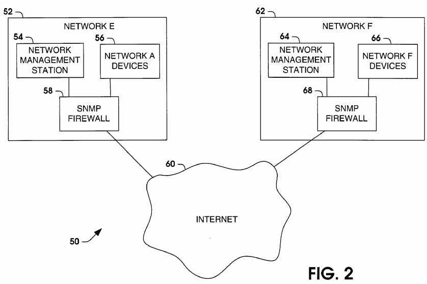
[0031] The SNMP firewall?58?can include the functionality for accepting the command from the network management station?54?and providing network community or network identification information into the command or SNMP packet. The SNMP packet can then be transmitted over the Internet?60?and intercepted by the SNMP firewall?68. The SNMP firewall?68?can intercept the SNMP packet, extract the network identification information and forward the SNMP packet to the network F device?66?corresponding to the IP address of the destination device in the SNMP packet. A response can then be provided by an SNMP agent residing on a destination device to the SNMP firewall?68. The SNMP firewall?68?provides the network identification information back into the packet and transmits the packet back to the network management station?54?through the Internet?60. Event information such as defined in a "TRAP" PDU can be transmitted in the same manner to the network management station specified in the SNMP firewall, the SNMP agent of the network device itself, or to the SNMP network management station that issued the last PDU request to the network device.
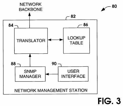
[0032]?FIG. 3?illustrates a system?80?for the transmission and receipt of SNMP messages by a network management station?82?in accordance with the present invention. The system?80?includes network management station?82?coupled to a network backbone. The network management station?82includes a user interface?90?coupled to an SNMP manager?88. A network administrator can transmit PDU commands and receive device status information through the user interface via the SNMP manager?88. The network management station?82?also includes a translator component?84?that utilizes a lookup table?86?to provide network identification information provided by the administrator via the PDU commands to the SNMP message being transmitted over the network backbone. The translator component?84?and the lookup table?86?also allow the SNMP manager?88?to determine network identification information and device IP address information in SNMP agent responses and event information from network devices residing in different networks.
[0033]?FIG. 4?illustrates a system?100?for the interaction of SNMP messages between an SNMP agent?112?and a network management station (e.g., SNMP manager) in accordance with the present invention. The SNMP agent?112?resides on a network device associated with a particular network. The SNMP agent?112?monitors operation and event information, for example, in a MIB data structure. The system?100?includes an SNMP firewall?104?that includes a map component?106?and a filter component?108. A network management station transmits an SNMP message across a network backbone. The SNMP message (e.g., PDU command) includes a device IP address in addition to network identifier information. The SNMP firewall?104?determines that the SNMP message is destined for a device within the SNMP firewall network. A filter?108?receives the SNMP message and utilizes a lookup table110?to resolve the actual IP address of the device that the SNMP message was directed.
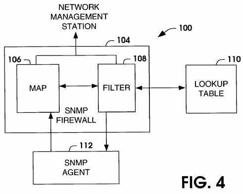
[0034] The SNMP agent?112?transmits response information based on a request from a PDU command from the network management station. Additionally, the SNMP agent?112?transmits event information defined by "TRAPS" residing in the SNMP agent. The map component?106?employs the lookup table to provide an address that includes network identification information in addition to the IP address of the device. The network identification information is then added to the SNMP response or event message so that the network management station can determine from which device and which network that the response and/or event information originates.
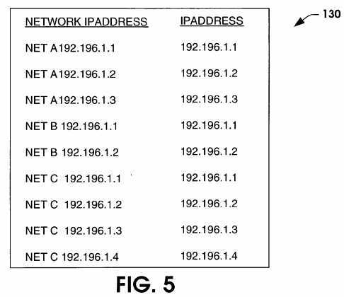
[0035]?FIG. 5?illustrates an exemplary lookup table?130?that includes network identification information in accordance with an aspect of the present invention. The exemplary lookup table?130?includes a network and IP address information row and an IP address only row relating to the IP address of destination devices. A network IP address includes the network identification information in addition to the IP address. The IP address of different devices in different networks can include the same IP address, but the devices can be differentiated by the network identification information. The network identification information can be provided in SNMP messages transmitted over an intranet or Intranet connection. The lookup table?130?includes the same IP address for many devices with differentiation being provided by the addition of network identification information. For example, a device in network A, B and C each employ the IP address 192.196.1.1. However, the present invention provides network identification information that allows PDUs to be executed with IP address information and network identification information, so that SNMP messages can be exchanged with multiple devices having the same IP address in different logical networks. An SNMP firewall can utilize the lookup table to resolve the actual IP address of the destination device.
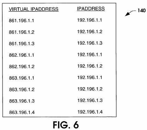
[0036]?FIG. 6?illustrates an exemplary lookup table?140?that includes virtual IP addresses corresponding to device IP addresses in different networks in accordance with an aspect of the present invention. The exemplary lookup table?140?includes a virtual IP address with a corresponding IP address relating to the destination device. A virtual IP address provides network identification information to the IP address. The IP address of different devices can include the same IP address, but the devices can be differentiated by the use of virtual IP addresses. The lookup table?140?includes the same IP address for many devices with differentiation be provided by using a virtual IP address that associates the actual IP address with network identification information. For example, a device in network A, B and C each employ the IP address 192.196.1.1. However, the present invention provides a virtual IP address that allows PDUs to be executed with virtual IP address information and the virtual IP address resolved by a corresponding SNMP firewall residing within the destination network. The virtual IP addresses allows a corresponding network to determine that the SNMP message is destined for a device in the destination network, so that SNMP messages can be exchanged with multiple devices having the same IP address in different logical networks.
[0037]?FIG. 7?illustrates an exemplary SNMP packet?150?having network identification information in accordance with an aspect of the present invention. The SNMP packet?150?includes a header?152, a network identifier?154, a device IP address?156?and an SNMP message?158. An administrator enters a PDU command at a network management station or some other device having an SNMP manager. The network management station builds a packet for transmission over the network (e.g., internet, Internet), which includes a destination device IP address?156?and a network identifier?154. The packet is then transmitted and received by the destination network having an SNMP firewall. The SNMP firewall removes the network identifier from the SNMP packet?150?and forwards the remaining portion of the SNMP packet to the destination device. If the packet is not destined for the network, the SNMP firewall ignores the packet.
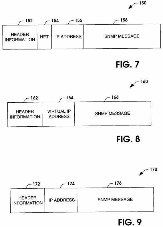
[0038]?FIG. 8?illustrates an alternate SNMP packet?160?having network identification information in the form of a virtual IP address in accordance with an aspect of the present invention. The network management station builds a packet for transmission over the network (e.g., internet, Internet), which includes a virtual IP address that corresponds to a device destination address and a network identifier. The SNMP packet includes a header?162, a virtual IP address?164?and an SNMP message?166. The packet?160?is then transmitted and received by the destination network having an SNMP firewall. The SNMP firewall resolves the virtual IP address by looking up a corresponding actual IP address, modifying the packet to include the actual IP address and forwarding the modified packet to the destination device. If the packet is not destined for the network, the SNMP firewall ignores the packet.?FIG. 9?illustrates an SNMP packet?170?that is transmitted to the destination device from the SNMP firewall. The SNMP packet?170?includes a header?172, a device IP address?174?and an SNMP message?176. The packet?170?is similar to a packet transmitted within a local area network (LAN). The response by the destination device can be rebuilt into a packet having the format illustrated in either?FIG. 7?or?FIG. 8, and transmitted back to the network management station.
[0039] It is to be appreciated that the present invention can be implemented into a system that is wireless or partially wireless in nature. Additionally, dynamic updates to the lookup tables can be provided when devices move from one network to another network. In mobile network environments, capabilities are required for allowing nomadic users to migrate from one logical network or sub-network to other logical networks or sub-networks without human interaction or network management interactions. As the mobile nodes move from one network to the other, the network identification needs to be updated, so that SNMP PDUs can be transmitted to the mobile node or mobile communication unit (MCU) at the proper network. Additionally, the network management station can provide updates to the system when fixed nodes are added to a network.
[0040]?FIG. 10?illustrates a mobile communication system?210?comprising a plurality of logical networks or subnetworks coupled to an ad-hoc backbone216?to form a parent network?218?(e.g., internet). The mobile communication system?210?includes a first logical network?220?having a network server222?and a second logical network?236?having a network server?238. The network server?222?includes an SNMP firewall (FW)?224?and a lookup table (LT)?226?for resolving SNMP messages having destination device IP addresses and network identification information. The network server?238?includes an SNMP firewall (FW)?240?and a lookup table (LT)?242?for resolving SNMP messages having destination device IP addresses and network identification information. A plurality of MCUs are associated with the logical networks?220?and?236. The MCUs can move between logical networks and the new network identification information for the MCU updated at one of the network server?222, the network server?238?or the network management station?212?in accordance with the present invention. The network identification information is then replicated to the lookup table?226?and the lookup table?242. For example, a replication engine?214?can replicate an updated lookup table and transmit the updated lookup table to the network server?222and the network server?238. For a fixed network device, the lookup table can be updated at the network management station?212?and replicated to the other nodes using the replication engine?214.
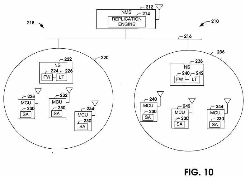
[0041] The first logical network?220?has a first MCU member?228, a second MCU member?232?and a third MCU member?234. The second logical network?236?has a fourth MCU member?240, a fifth MCU member?242?and a sixth MCU member?244. As is conventional, each MCU associates itself, typically by registration, with a logical network coupled to the ad-hoc backbone?216, such that a link is formed between itself and other devices situated on the ad-hoc backbone?216. A geographic cell defines a region of coverage in which successful wireless communication can occur. Depending on the type of antenna selected, output power and RF sensitivity of a respective access point (not shown), the geographic cell may take one of several different forms and sizes.
[0042] Each MCU includes an SNMP agent (SA)?230?that monitors operation and event information associated with the MCU. Additionally, the SNMP agent?230?can also respond to SNMP requests from the network management station?212. The messages are transmitted across the ad-hoc backbone216?and received by the SNMP firewall?224?or?240?of the destination network, which employs the lookup table?226?or?242?to pass the SNMP message to the appropriate MCU. The SNMP firewall?224?or?240?uses the lookup table?226?or?242, respectively, to update the response of the SNMP agent with network identification information. Additionally, the SNMP agents?230?can provide status information to the network management station?212. The SNMP firewall?224?or?240?also uses the lookup table?226?or?242, respectively, to update the event information with network identification information. As MCUs move from one network to the other, the network identification information is provided to the network management station?212?and the lookup tables?226?or?242?are updated dynamically, for example, via the replication engine?214.
[0043] In view of the foregoing structural and functional features described above, methodologies in accordance with various aspects of the present invention will be better appreciated with reference to FIGS.?11-12. While, for purposes of simplicity of explanation, the methodologies of FIGS.?11-12are shown and described as executing serially, it is to be understood and appreciated that the present invention is not limited by the illustrated order, as some aspects could, in accordance with the present invention, occur in different orders and/or concurrently with other aspects from that shown and described herein. Moreover, not all illustrated features may be required to implement a methodology in accordance with an aspect the present invention.
[0044]?FIG. 11?illustrates a methodology for transmitting an SNMP message from a network management station in accordance with an aspect of the present invention. The methodology begins at?300?where a network administrator enters an SNMP command that includes network identification information. The methodology then proceeds to?310. At?310, the network management station then builds an SNMP packet with destination device address information and network identification information built into the SNMP packet. For example, the SNMP packet can include a network identifier built into the packet and an IP address corresponding to the destination device for the SNMP packet. Alternatively, the SNMP packet can include a virtual IP address that corresponds to an actual IP address and a particular network. A lookup table can be provided in either case to match IP address information without network identification information with IP address information with network identification information. The methodology then proceeds to?320. At?320, the SNMP packet is transmitted over the network backbone of the multi-network system (e.g., intranet, Internet).
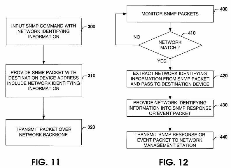
[0045]?FIG. 12?illustrates a methodology for determining a destination device for an SNMP packet in a multi-network system having the possibility of duplicate IP addresses in different networks in accordance with an aspect of the present invention. The methodology begins at?400?where SNMP packets are monitored at a network in a multi-network system. It is to be appreciated that multiple networks can be monitoring the SNMP packets concurrently. At?410, the methodology determines if network identification information corresponds to the monitoring network, such that the SNMP packet is destined for a device in the monitoring network. If the SNMP packet does not include network identification information corresponding to the monitoring network (NO), the methodology returns to?400?to continue monitoring SNMP packets. If the SNMP packet does include network identification information corresponding to the monitoring network (YES), the methodology proceeds to?420.
[0046] At?420, the network identification information from the SNMP packet is extracted, and the SNMP packet is forwarded to the destination device based on the IP address of the destination device in the SNMP packet. For example, the network information can be provided as a network identifier field residing in the SNMP packet. Alternatively, the network information can be provided by associating a virtual IP address with a device and its associated network. The network then proceeds to?430. The destination device then provides a response to the SNMP packet via an SNMP agent. At430, the methodology provides network identification information into an SNMP response packet. Alternatively, the response packet can be an SNMP event packet containing event information defined by one or more "TRAP" PDUs. At?440, the SNMP response or event packet is transmitted to the network management station.
[0047] In order to provide a context for the various aspects of the invention, FIG.13?and the following discussion are intended to provide a brief, general description of a suitable computing environment in which the various aspects of the present invention may be implemented. While the invention has been described above in the general context of computer-executable instructions of a computer program that runs on a computer, those skilled in the art will recognize that the invention also may be implemented in combination with other program modules.
[0048] Generally, program modules include routines, programs, components, data structures, etc. that perform particular tasks or implement particular abstract data types. Moreover, those skilled in the art will appreciate that the inventive methods may be practiced with other computer system configurations, including single-processor or multiprocessor computer systems, minicomputers, mainframe computers, as well as personal computers, hand-held computing devices, microprocessor-based or programmable consumer electronics, and the like. The illustrated aspects of the invention may also be practiced in distributed computing environments where tasks are performed by remote processing devices that are linked through a communications network. However, some, if not all aspects of the invention can be practiced on stand-alone computers. In a distributed computing environment, program modules may be located in both local and remote memory storage devices.
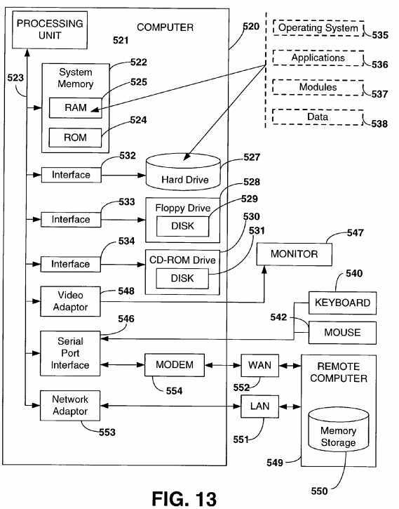
[0049] With reference to?FIG. 13, an exemplary system for implementing the various aspects of the invention includes a conventional server computer520, including a processing unit?521, a system memory?522, and a system bus?523?that couples various system components including the system memory to the processing unit?521. The processing unit may be any of various commercially available processors. Dual microprocessors and other multi-processor architectures also can be used as the processing unit?521. The system bus may be any of several types of bus structure including a memory bus or memory controller, a peripheral bus, and a local bus using any of a variety of conventional bus architectures. The system memory includes read only memory (ROM)?524?and random access memory (RAM)?525. A basic input/output system (BIOS), containing the basic routines that help to transfer information between elements within the server computer?520, such as during start-up, is stored in ROM?524.
[0050] The server computer?520?further includes a hard disk drive?527, a magnetic disk drive?528, e.g., to read from or write to a removable disk?529, and an optical disk drive?530, e.g., for reading a CD-ROM disk?531?or to read from or write to other optical media. The hard disk drive?527, magnetic disk drive?528, and optical disk drive?530?are connected to the system bus?523?by a hard disk drive interface?532, a magnetic disk drive interface?533, and an optical drive interface?534, respectively. The drives and their associated computer-readable media provide nonvolatile storage of data, data structures, computer-executable instructions, etc. for the server computer?520. Although the description of computer-readable media above refers to a hard disk, a removable magnetic disk and a CD, it should be appreciated by those skilled in the art that other types of media which are readable by a computer, such as magnetic cassettes, flash memory cards, digital video disks, Bernoulli cartridges, and the like, may also be used in the exemplary operating environment, and further that any such media may contain computer-executable instructions for performing the methods of the present invention.
[0051] A number of program modules may be stored in the drives and RAM?525, including an operating system?535, one or more application programs536, other program modules?537, and program data?538. A user may enter commands and information into the server computer?520?through a keyboard540?and a pointing device, such as a mouse?542. Other input devices (not shown) may include a microphone, a joystick, a game pad, a satellite dish, a scanner, or the like. These and other input devices are often connected to the processing unit?521?through a serial port interface?546?that is coupled to the system bus, but may be connected by other interfaces, such as a parallel port, a game port or a universal serial bus (USB). A monitor?547?or other type of display device is also connected to the system bus?523?via an interface, such as a video adapter?548. In addition to the monitor, computers typically include other peripheral output devices (not shown), such as speakers and printers.
[0052] The server computer?520?may operate in a networked environment using logical connections to one or more remote computers, such as a remote client computer?549. The remote computer?549?may be a workstation, a server computer, a router, a peer device or other common network node, and typically includes many or all of the elements described relative to the server computer?520, although only a memory storage device?550?is illustrated in?FIG. 13. The logical connections depicted in?FIG. 13?include a local area network (LAN)?551?and a wide area network (WAN)?552. Such networking environments are commonplace in offices, enterprise-wide computer networks, intranets and the Internet.
[0053] When used in a LAN networking environment, the server computer?520?is connected to the local network?551?through a network interface or adapter?553. When used in a WAN networking environment, the server computer?520?typically includes a modem?554, or is connected to a communications server on the LAN, or has other means for establishing communications over the wide area network?552, such as the Internet. The modem?554, which may be internal or external, is connected to the system bus?523?via the serial port interface?546. In a networked environment, program modules depicted relative to the server computer?520, or portions thereof, may be stored in the remote memory storage device. It will be appreciated that the network connections shown are exemplary and other means of establishing a communications link between the computers may be used.
SRC=http://www.freepatentsonline.com/y2004/0044758.html
PatentTips - SNMP firewall,布布扣,bubuko.com
标签:des style blog http color 2014
原文地址:http://www.cnblogs.com/coryxie/p/3819313.html