标签:
This paper proposed a system for a real sense 3D facial reconstruction method based on multi-view stereo vision generated using an orthographic 3D model. Multi-view stereopsis is an effective technology for expanding perspective and reducing noise. The presented multi-view stereo vision is implemented as a multi-view stereo vision using calibration, stereo matching, combining, reconstruction and texture mapping procedures. This paper makes a systemic contribution and two technical contributions. Its systemic contribution is that it demonstrates a state-of-the-art passive stereo vision system for meaningful orthographic 3D facial reconstruction. We have tested our method on various subjects, including two actors and an artificial plastic human head model. The primary technical contribution is an algorithm that combines stereo vision data based on clustering, which includes the following procedures: outlier detection, filling and data combining. The second contribution is a multi-view calibration method, which results in an orthographic position model. An orthographic position is an important requirement and is useful in various medical fields, e.g., maxillofacial surgery research. In addition, we describe a cluster sampling algorithm for undersampling point clouds. The presented sampling algorithm keeps data on an average distribution. A quantitative evaluation proves that the system is an effective, low-cost and high-resolution solution to reconstructing a 3D face model without markings or structured light.
Keywords: multi-view stereo vision, 3D face reconstruction, orthographisch 3D model
Facial modeling has generated widespread attention, producing a variety of applications in various fields, including virtual reality, animation, and medicine. Acquiring, modeling, and compounding a 3D face and the related dynamic analyses have become an active research topic in computer
vision and computer graphics research [1]. Many applications have arisen in clinical fields since the initial development of 3D facial imaging equipment [2], including facial average generation, gender analysis, facial growth, craniofacial anomalies, and orthognathic surgery. Facial averages evolve from clinical imaging for the purpose of diagnosis and prediction, creating an average template based on the external measurements of normal faces. In addition, 3D facial averages can be used to generate a gender analysis bias from differences in human cheeks, brows and lower face between different gender average faces. Furthermore, 3D facial models are used to predict the change in soft facial tissue in orthognathic surgery.
Capturing and processing human geometry is the principal task and presupposition of several applications. There have been various acquisition system process pipelines sharing common basic theory and implementation details. Despite the existence of a large number of studies, realistic
facial reconstruction still faces considerable challenges because human faces are globally similar in terms of the position of main features (e.g., eyes, mouth, nose). Other important criteria are sensor costs, spatial and/or temporal resolutions, the manner of sensor use (cooperative or not),
and intrusiveness. These criteria are particularly important in the medical field.
Inspired by previous research (numerous methods have been proposed in the literature, and a few of them are discussed in Section 1.2), and in consideration of important requirements in medical applications, such as sensor cost, spatial temporal resolutions, and intrusiveness, we present a system for an orthographic 3D facial reconstruction method based on multi-view stereo vision. The proposed system includes multi-view stereo calibration, Normalized Cross Correlation (NCC) matching, combined data, 3D reconstruction, and texture mapping. The method requires
a consumer digital camera but no other special equipment, such as a laser or structured light. Our method ultimately e±ciently reconstructed an orthographic real sense 3D face triangle mesh with a low cost and high resolution. Our system is a consumer device; however, our method exhibits numerous advantages, such as being entirely passive and not requiring markings, drawings, or structured light; of critical importance is the fact that our result is an orthographic 3D face model. An orthographic position is a critical requirement and is useful in the medical field, e.g.,
in maxillofacial surgery research.
There are several acquisition techniques in the literature that are general or are dedicated to specific objects. In early research, the most widely used acquisition systems for faces were based on structured light, were highly reliable when recovering complex surfaces and were highly accurate. Digital 3D photogrammetryle (3dMD) combined the technology of stereo vision and structured light using three cameras (a color camera and two infrared cameras) to project random light on an object [2]. Similarly, Ayoub, A., et al. proposed a method that does not require detailed
illumination designs but does require additional structured lighting [3]. In contrast, DI3DTM stereophotogrammetry surface imaging systems [4] do not require texture projections; they only require four high-resolution color images and can rebuild a 3D facial model in 5 min.
C Rocchini et al. (2001) proposed a low-cost 3D scanner based on structured light. It adopts a set pattern of recursive subdivisions that mix thin stripes and colored bands. An important feature of the scanner is its ability to acquire self-registered and high-resolution shape and color data. Nevertheless, the objects must be static for 6 min, which restricts its application.
The passive approach is becoming increasingly popular with increases in camera resolution. Stereo matching is a core issue of stereo vision 3D reconstruction. Furukawa Y, Ponce J presented a multi-view stereopsis [5], where they regarded multi-view stereo as three steps: single stereo
matching, expansion and filtering. In the stereo matching stage, a series of feature were detected using Harris and DOG. Then, stereo matching was performed on all stereo pairs, and a series of signi¯cant feature patches were produced. In the expansion stage, expanding the initial matching adjacent domain produced dense results based on a series of sparse results acquired in the front. In stage three, a filter that relies on visibility consistency to remove outliers was applied. By iterating between expansion and ¯ltering steps, their method could process complicated surfaces and reject outliers more effectively, and it did not need any form of initialization (e.g., visual hull, bounding box, disparity range). Another feature of the algorithm is that it estimates the normal of the face, which is important to weak textures, and maintains the performance in the presence of weak textures, obvious defects and higher curvatures.
Bradley et al. proposed binocular stereo reconstruction for faces based on an iteration method [6], where they combined seven pairs of standalone stereo vision sources into a high-resolution facial model. Under controlled lighting conditions, they captured facial images with seven pairs of cameras, where every pair only captured a portion of a human face. Every pair of images employs iterative constraint stereo matching, smoothing with a large nuclear Gaussian distribution, and again performing iterative constraint stereo matching to outliers. A point cloud was synthesized using hierarchical clustering undersampling, outlier removal and triangular mesh reconstruction.
Beeler et al. proposed an important 3D face reconstruction system [7]. Their significant contribution was to propose a suitable refinement algorithm, combining facial data consistency and surface patch consistency. Their solution provided another contribution in that it included an
easy spherical object calibration method. Their system contained four cameras and a consumer binocular-stereo camera; combined a three-point cloud obtained by three stereo matching, self-governed pair visions; and reconstructed a triangle mesh with a Poisson method. They used an
iterative refinement method to enhance details and restore facial features. The system was later extended to the dynamic expression sequence [8].
This paper makes a systemic contribution and two technical contributions. The systemic contribution is to demonstrate a state-of-the-art passive stereo vision system for orthographic 3D facial reconstruction. The orthographic position is a critical requirement in the medical field. We
demonstrate that face scanning accomplished using a consumer camera exhibits numerous benefits, such as being entirely passive, high resolution, single shot, low cost, and easy to deploy as well as requiring no marks and no drawing. The primary technical contribution is an algorithm that combines stereo vision data based on clustering, which includes outlier detection, fill and data combining, the details of which are described in 2.3. The second contribution is the multi-view calibration method in 2.1, which results in an orthographic position 3D model. An orthographic position is a critical requirement and is useful in the numerous medical fields, e.g., maxillofacial surgery research. We also describe a cluster sampling algorithm to undersample point clouds. The presented sampling algorithm keeps data on an average distribution.
Computer stereo vision is the technology to extract 3D information from digital images. By comparing pixels of a scene from a pair of images, 3D information can be extracted by examining the relative positions of objects in the two panels. In order to get a wider perspective in a limited space and improve the quality of the reconstruction, multi camera pairs were implemented in this paper. Our multi-view stereo vision sensor comprises of five cameras (see Figure1). For facilitate, they are named respectively as LU (left up), LD (left down), RU (right up), RD (right down) and CC (center) bias of their positon. LU and LD compose of a binocular stereo pair named G1, similarly RU and RD compose of another binocular stereo pair G2. It can get a suitable visual angle to take a rounded face photos if only G1 and G2 hold an enough larger distance. We develop Zhang, ZY[9] algorithm to calibrate multi-view stereo vision sensor as following: firstly, the left pair and right pair of stereo vision sensor are calibrated independently, then, two calibrated vision sensor pairs are calibrated again since a binocular-stereo pair(two sensors) is regarded as an integer. By means of two coordinate systems’ geometrical relationship, they are transformed in a uniform coordinate system. The pipeline of our method composing of the six steps in sequence is illustrated in Figure2).

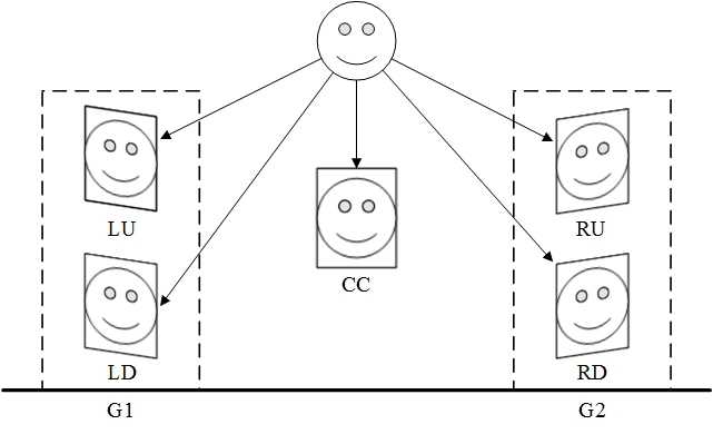
Fig. 1: Multi-view stereo vision sensor

Fig. 2: Pipeline of multi-view real sense face reconstruction. (a) Calibrate multi-view stereo vision
sensor. (b) Capture images with our multi-view stereo vision sensor. (c) Generate dense disparity maps
by stereo matching two images in a pair. (d) Combine left data and right data. (e) Apply reconstruction
method to obtain triangular mesh. (f) Map texture to mesh and get a real sense face model
Camera calibration is an important task in 3D computer vision, particularly when metric data are required for applications involving accurate dimensional measurements. We developed Zhang, ZY[9]algorithm to calibrate multi-view stereo vision sensor: firstly, calibrate the left pair and right pair of stereo vision sensor respectively and independently. Secondly, two calibrated coordinate were regarded as a stereo pair and calibrate again, they were unified in a coordinate system. This approach can be extended to more stereo pairs, we just implement two pairs. At last, we aligning coordinate system to the center camera’s coordinate. The purpose of this setup is making final model hold orthographisch pose. The detail of our algorithm represented as following.
2D point is denoted by , and 3D point is denoted by . A camera is modeled by the usual pinhole model: The relationship between a 3D point M and its image projection m is given by
(1)
Where is point in the world, m0 as its projection in the camera’s coordinates, named physical coordinate, is projection in pixel coordinate system. acts as a scale factor, called camera’s extrinsic parameters and A called its intrinsic parameters., and the main objective of calibrating is solve A. For calibration of binocular vision sensor, assume a point in the world, its projection in two cameras coordinate systems of a stereo pair were and , obviously:
(2)
(3)
Than we can get geometrical relationship (rotation matrix and translation matrix) between two physical coordinate systems:
(4)
Define that
(5)
(6)
where and express the geometrical relationship. All parameters can get by optimize following function:
(7)
Where represents times imaging and represents corner point in the equation. Note, this equation doesn’t consider distortion coeffcients, more details can obtained in reference[9].
After calibrate of stereo vision sensor in a pair, two sensors’ coordinates transform to a coordinate system. Assume objects located in the world coordinate system respectively are and , as shown in 3. Calibration of among pairs aim to consolidation depth information by calculate the geometric transformation and between and where is a rotation matrix, and is a translation matrix.
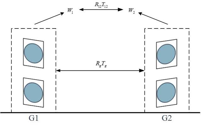
Fig. 3: Calibration among groups
The following calculation was conducted after stereo images rectification. In calibration between two pairs, and consider as an integration, hence solving geometrical relationship between two pairs can regard as a stereo calibration problem. We can get the rotation matrix and translation matrix of between calibrated space by solve equation (7). According to the above calculated parameters, geometrical relationship between points in calibrated space is founded:
(8)
Than rotation matrix and translation matrix between world coordinate systems and can be derived:
(9)
(10)
Although we only deduce calibration of two pairs, our calibration method of multi-view stereo vision sensor can easily extends to more pairs. Once to calculate the geometric trans formation between all neighborhood groups, all spatial disparity fields can join in by a simple cascading the coordinate space.
For example as shown in the Figure4, supposing G2 is a reference spatial systems, we can get transformation matrix of G4 to G2 by transformation matrix of neighborhood pairs G3 to G2 firstly and then transformation matrix G4 to G3, the result through coordinate cascading rules:
(11)
(12)
The last setup of our method is transform coordinate system to center signal camera’s (that mean camera CC, see Figure 1) coordinate system. The purpose of this setup is making final model hold orthographisch pose. The approach of the transform similar to above transformation expression by rotation matrix and translation matrix, as illustrate with Figure 4, on behalf of the local coordinates. In order to guarantee an orthographisch position, we ask testee look at his eyes in the mirror (see Figure 7) upon camera CC strictly. And the CC is parallel to mirror surface strictly. Thus, camera CC’s coordinate is an orthographisch. After transforming 3D model to CC’s coordinate by using calibrate result, we obtain an orthographisch 3D model.
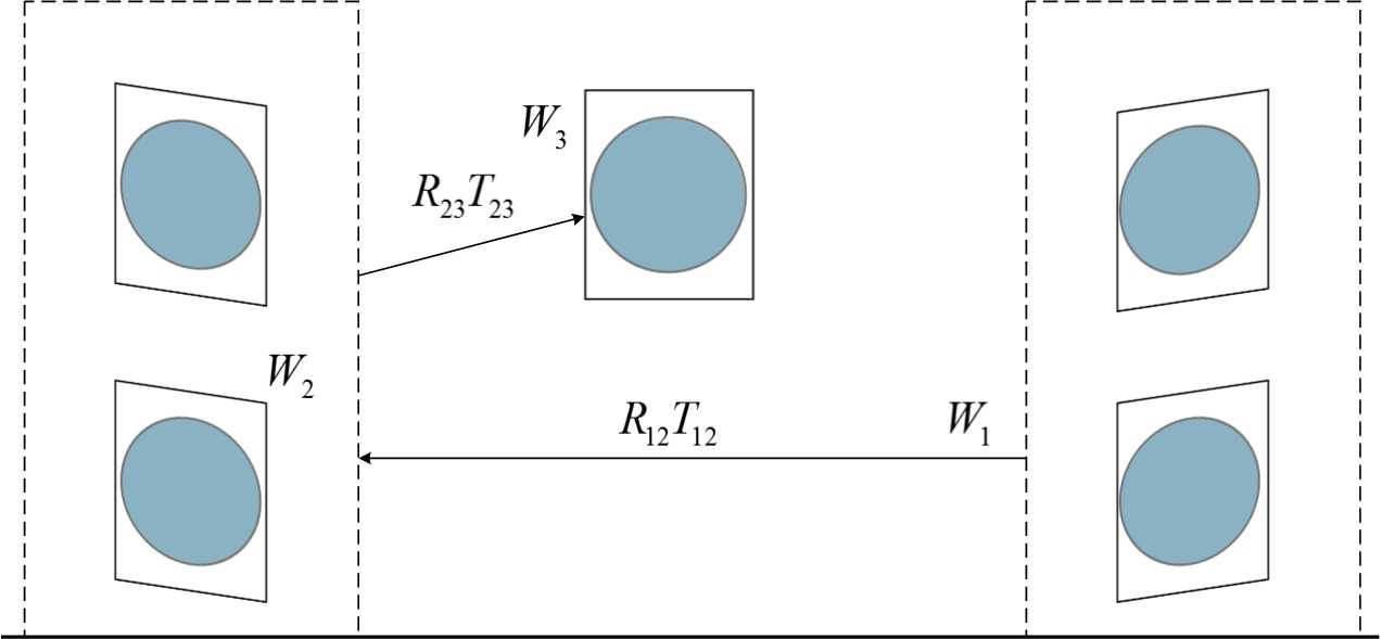
Fig. 4: Align among groups
Our stereo match algorithm similar to[5], which is implemented at multi-resolution framework. Biased on the assumption face surface smoothness, ours is two difference to theirs: one is we not smoothing disparity map at each level pyramid ended, another is we combine overlay region. For each image pair, the views are first rectified [10]. For each pixel in the rectified primary view, we then find the closest matching pixel on the corresponding epipolar line in the rectified reference view. Specially, we assume brightness constancy, and use multi-resolution normalized cross correlation (NCC) on square pixel regions in order to improve efficiency and accuracy, specific process is as follows.
match. Low resolution stereo match result as the initialization of high resolution (the lowest resolution is uninitialized). Processing flow is Identical in each resolution layer, a metric for the best match is:
(13)
where and are local neighborhoods of size (we select size based experience) in the primary and the reference view, and and represent the intensity averages over the same neighborhoods. We ignore very bad matches by thresholding the NCC metric to the range of [0.5 - 1]. Three channels’ NCC are calculated respectively for color images and taking the biggest one as the pixel’s NCC.
constraint. After applying local NCC match, we detect error of the intermediate result under rules of smoothness constraint, ordering constraint, left to right and right to left consistency checking.
fill. In order to correct inconsistency in boundary overlapping region, we using following clustering based data combine algorithm, described in section2.3. We divide two disparity data into two cells sets, and calculate every cell’s value ,cell’s value equal to points’ numeration. Empty cell (cell’s vaule equal to 0) is filled with opposite side cell’s value (i.e. if empty cell in right side set, fill with the value of corresponding cell in left side set, and vice versa). In case of corresponding cells in two sets are both empty, fill the cell with the point of the cell’s geometric center position.
rematch. In this step, each point new added must match again under constraint conditions, and its disparity re-determine by neighborhood. The process (filling and rematch) can be repeated several times until get a satisfactory result. Figure5 demonstrates the process.
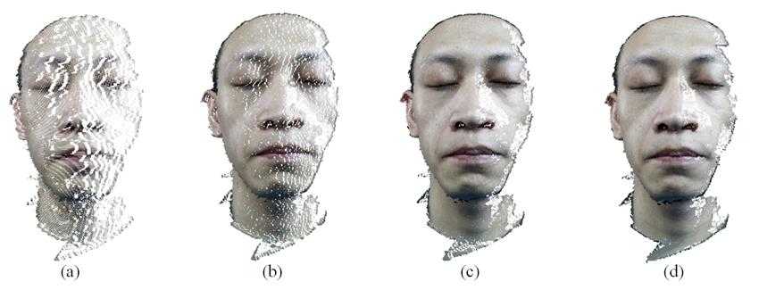
Fig. 5: Iterative NCC fill: (a) 1st fill result; (b) 2nd fill result; (c) 3th fill result; (d) 4th fill result
Although multi-view stereo vision solution can solve the occlusion problem caused by region of nasal line or other, but in the meanwhile it brings data combine problem. We proposed clustering combine data algorithm to solve the problem. The clustering combine data algorithm works as following.
divide two point cloud into grid cells. We firstly divide two point cloud into grid cells based on a certain size (i.e. the size of a pixel). A cell named a cluster, and its value equal to numbers of point in a cell, Figure 6 displays this approach(a cell is actually infinitesimally small and grids are numerous).
remove the abnormal values. Secondly, we calculate the value of each cluster in two cells sets, remove the abnormal values cluster, empirical, we remove clusters which value is too small (i.e. value < smallestValue * 1:2 ).
add two point cloud together. Corresponding clusters are added together to seek a maximal connected set by morphologic analysis, then holes in the connected set are filled through interpolation.
re-calculate NCC. Then, for overlapping region, we combine points from two pairs stereo vision sensors and calculate corresponding points’ NCC. A point with larger NCC is preserved, meanwhile, the point whit smaller NCC was abandoned.
filter. At last, we apply Gaussian filtering to fused point cloud, severely changeable point was replaced by mean of its neighbourhood. The most advantage of the method is it doesn’t need estimate a point whether visible or not.
In this section, we describe our method for generating a triangle mesh from the unorganized point cloud obtained with pairs of binocular stereo.
Considering performance, we use downsampling method before reconstruction. After merging of the depth maps, the resulting point cloud contains large amounts of redundant information due to oversampling of smooth regions, as well as duplicate reconstructions of parts of the geometry from multiple views. In order to quickly and adaptively remove the redundant information, we apply a cluster sampling[11] to . One version of cluster sampling is area sampling or geographical cluster sampling. Cluster sampling is a sampling technique used when ”natural” but relatively homogeneous groupings are evident in a statistical population. In this technique, the total population is divided into these groups (or clusters) and a simple random sample of the groups is selected. Then the required information is collected from a simple random sample of the elements within each selected group. This approach in our implementation works as follows:
1. compute a bounding box around ;
2. determine a cell size for split ’s side into ;
3. separate into non-overlapping subsets, every subset is a cube with size of ;
4. allocate to subsets according to point’s coordinate in the corresponding sub-cube, every subset as a cluster;
5. determine clustering criteria, here we use nearest to center;
6. select clusters need extract on the basis of vertex in ;
7. extract points from clusters based on clustering criteria.
After the above processing, we obtained the unorganized sampling point cloud with our multi-view stereo vision sensor. Further, applying Poisson reconstruction [12], a triangle mesh generated from the point cloud. Poisson reconstruction creates very smooth surfaces that robustly approximate noisy data.
Fig. 6: Divide point cloud into cells
In order to get real sense, we need mapping texture on triangle mesh model yet reconstructed. Projecting all vertices to corresponding pixels in the images, pixels’ coordinates can transform to textures’ coordinates. For texture is not an overall set but N subsets in multi-view stereo vision, N is pairs of stereo vision, our texture mapping for multi texture sets method presents as: calculate cross product of a vertex’s normal and pixel’s normal in N textures, get angles’ array ; separate the triangle mesh into N connected sets based on minimum cross product in ; mapping vertices in every connect set to its corresponding pixel in corresponding texture set.
In this section, we demonstrate our multi-view stereo algorithm with several reconstructions and specific implement procedure.
The grouping of cameras in binocular pairs is arranged in a ring setup, composed of four Canon EOS550D cameras and one Canon EOS600D as shown in Figure 7. The studio setup makes it well-suited for facial photography since straightforward face to object. There are two Canon 550D cameras on each side, subtend an angle of about 30 at the head’s coronal plane and one Canon 600D camera on the frontal view of the face subtend an angle of 90 at the head’s coronal plane and about 90 centimeter from the nose. The cameras were synchronizable to 0.1 seconds, which is sufficient time for taking static subjects.
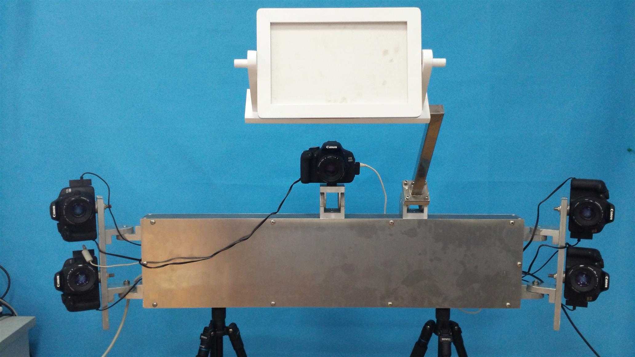
Fig. 7: Stereo vision sensor device
We handle this by working in a darkened studio, four soft light boxes are arranged around the front view of object and a reflectors on ground to light chin. The cameras in the studio setup were manual focus, prime lenses and they were focused and calibrated just once for objects. We using black and white checkerboard calibration plate with angular points, the size of each lattice is . For an ideal calibration result, we take 20 calibration template images from different direction at the same time. Camera CC just used for fixed orthographic position, see Figure 1. In order to make sure take front elevation view image, we ask testee look at his eyes in mirror (see Figure 7) upon camera CC strictly.
We refinement the triangle mesh face model and fairing process. Refinement algorithm can reference to [7]. Then we perform our evaluation on the artificial human head model using 3D face reconstruction system described above. Figure 8 shows the artificial plastic human head. Meanwhile, we reconstruct 3D face model of the artificial human head model with Artec SpiderTM [13] as ground-truth model (golden standard data). Artec SpiderTM is a white light 3D scanner and its’ common specifications as follows: 3D resolution up to 0:1mm, 3D point accuracy up to 0:05mm, 3D accuracy over distance up to 0:03% over 100cm, texture resolution up to 1:3mp. Figure 8 shows the ground-truth model.
Error is measured as perpendicular distance between the ICP registered [14] ground-truth model and reconstructed model. A visual comparison of the ground-truth and recovered models is shown in Figure 8: (a) is the ground-truth of 3D face model via white light 3D scanner; (b) is the reconstruction with our stereo vision system; (c)is a distribution of the absolute error between the model via white light 3D scanner and the registered model by our stereo vision system. Figure 8 illustrates the recovered geometry is substantially correct yet the details in the reconstructed model are slightly less defined. Table 1 lists the errors statistics, 95% points’ error are less or equal to 0.5mm and 97% points’ error are less or equal to 1.0mm.
Measured errors are not directly applicable to real faces because the surface reflectance of the artificial human head model is different from truly human skin. Our algorithm did not reconstruction regions like the nostrils, where is interior invisible in the images. The error statistics include these regions, because we include this source in consideration of validated the objectivity of the result, yet the errors are an over-estimate in the sense.
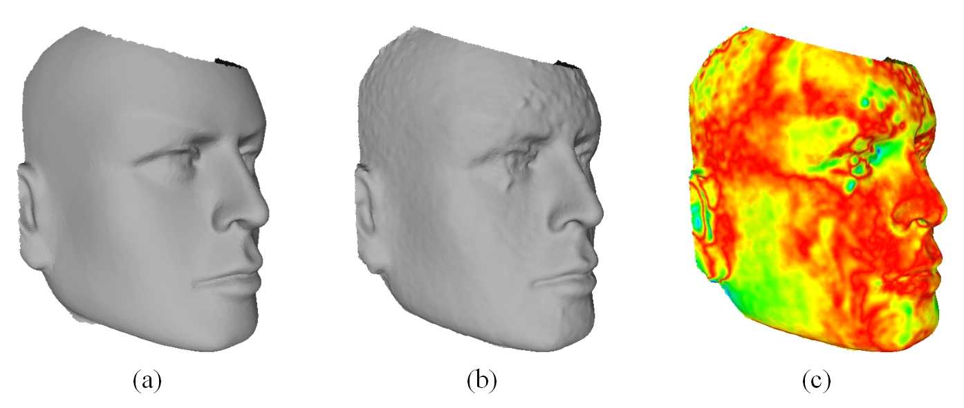
Fig. 8: (a) 3D face model of the artificial human head model via white light 3D scanner; (b) reconstruc-
tion with our stereo vision system (c) distribution of the absolute error between the model via white
light 3D scanner and the registered model by our stereo vision system
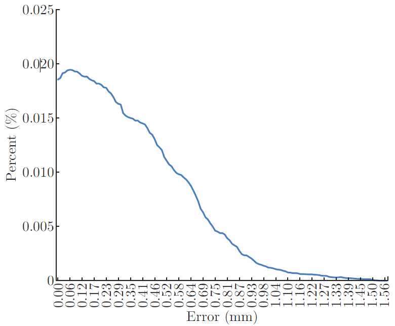
Fig. 9: Errors distribution
Table 1: Errors statistics
|
Average(mm) |
<0:5 (mm) |
<1 (mm) |
|
0.3970 |
95% |
97% |
We perform our evaluation on two actors with a variety of facial expression, Figure 10 demonstrates reconstruction of the various objects. Figure11 demonstrates an actor’s different express include original face images and model both with and without texture.
Figure12 demonstrates different views of recovered 3D face model, which proves our system sophisticated reconstructed a 3D face model. Figure 13 shows micro deformation detail of mesoscopic in wrinkle areas as well as their consistency in regions that do not undergo deformation. Two extreme zoom renderings, are shown, Figure 13(b) reveals eye and Figure 13(c) reveals dimple).
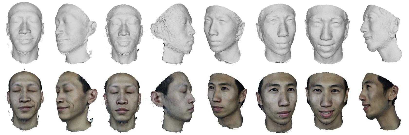
Fig. 10: Recovered models and synthesized views, for viewpoints different from the original camera
images, across subjects of varying appearance
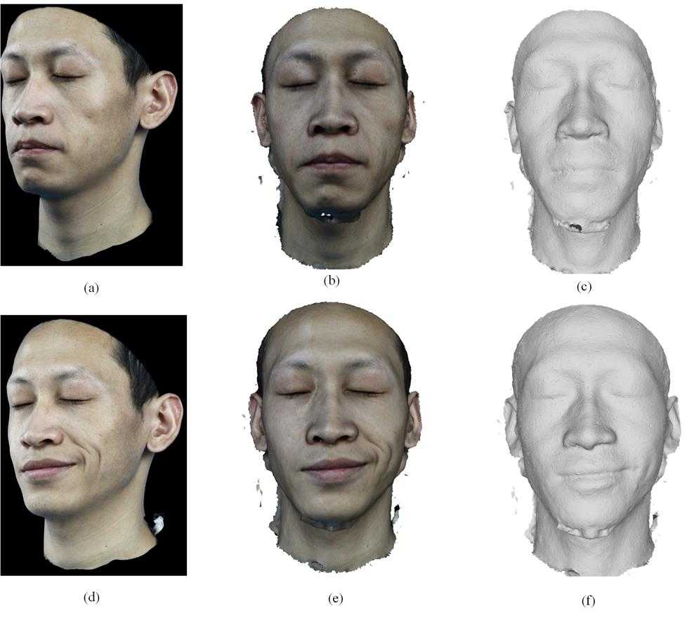
Fig. 11: Recovered models of a subject for two different express
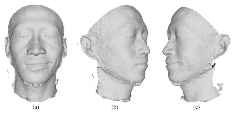
Fig. 12: Different views of a model with fixed illumination
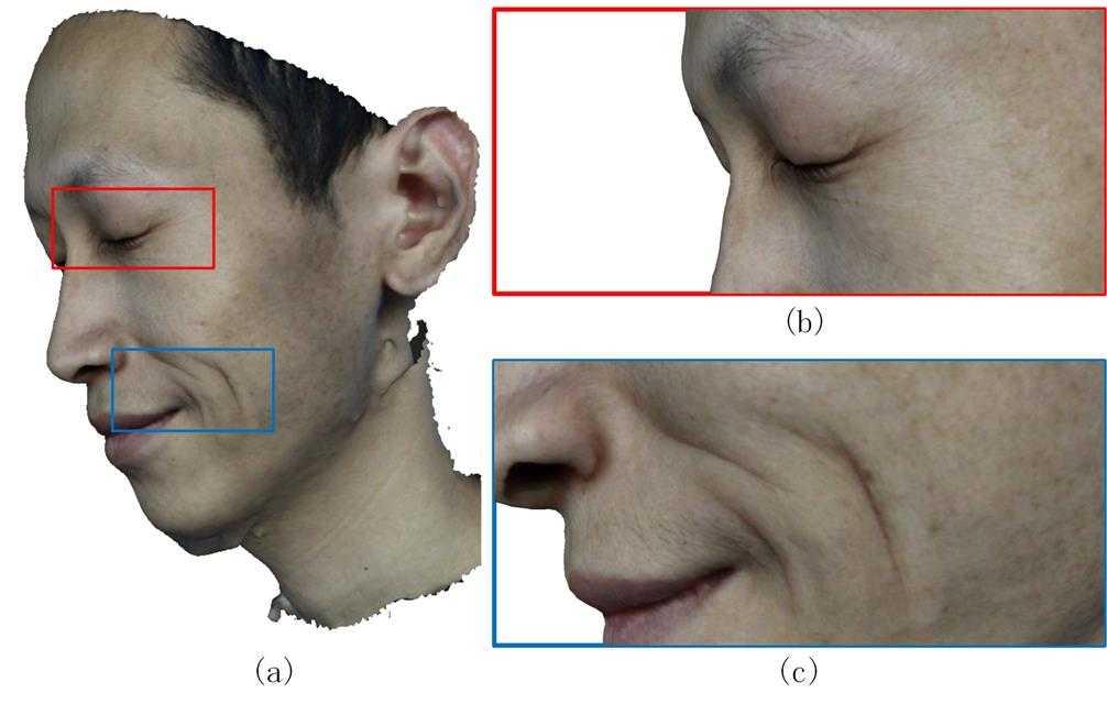
Fig. 13: Megapixel textures allow extremely close zoom renderings (middle and right)
Unlike methods that require markers, face paint, structured light, or expensive hardware, we use only five consumer digital camera and four soft light illumination box. Nonetheless, our methods yield good quality face models, providing evidence that our multi-view stereo vision is a reliable way to reconstructed 3D real sense face model.
Once calibrated, our system is automatic works without the need to tune the software for individual cases only if cameras’ position changed. We just need take face photos but not require manual processing to reconstruct a mesh. Our method is available for various objects, we demonstrate by reconstructing three different facial performances given by different actors, and including very different deformations.
Specularity on the face is a problem when capturing images under general lighting and specular areas typically distort the mesh. For example, reflects a bright light source often occurs at the tip of the nose. To deal with this, solution include preventing it from happening in the first place: using indirect lighting or cross-polarization, or post-processing to explicitly detect the affected area.
In addition, higher resolution cameras, and more camera pairs are needed, they would lead to higher quality. Correctly capturing the eye geometry, including eyelashes and eyebrows, would produce even more realistic results. Besides that, our method is not designed to reconstruct facial hair.
We present a purely passive system of 3D real sense face reconstruction based on multi-view stereo vision, generated an orthographisch 3D model. We have tested our method on various subjects including two actors and an artificial plastic human head model. A quantitative evaluation proves the system is an effective, low-cost and high resolution solution to reconstruct 3D face model without maker, structured light.
A real sense 3D face reconstruction system based on multi-view stereo vision
标签:
原文地址:http://www.cnblogs.com/junzhang-uestc/p/4632602.html