标签:which processes cond deb rar protect within out 包含
Extensible Linking Format(ELF)
ARM ELF映像包含sections, regions, and segments,每个链接阶段都有不同的映像视图。
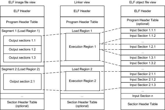
An object or image file is constructed from a hierarchy of input sections, output sections, regions, and program segments.
Image regions are placed in the system memory map at load time. The location of the regions in memory might change during execution.
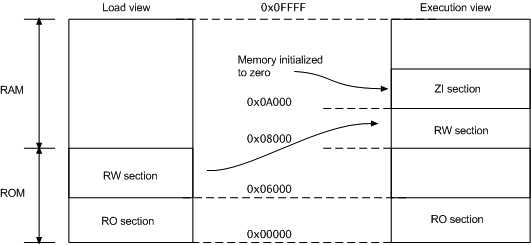
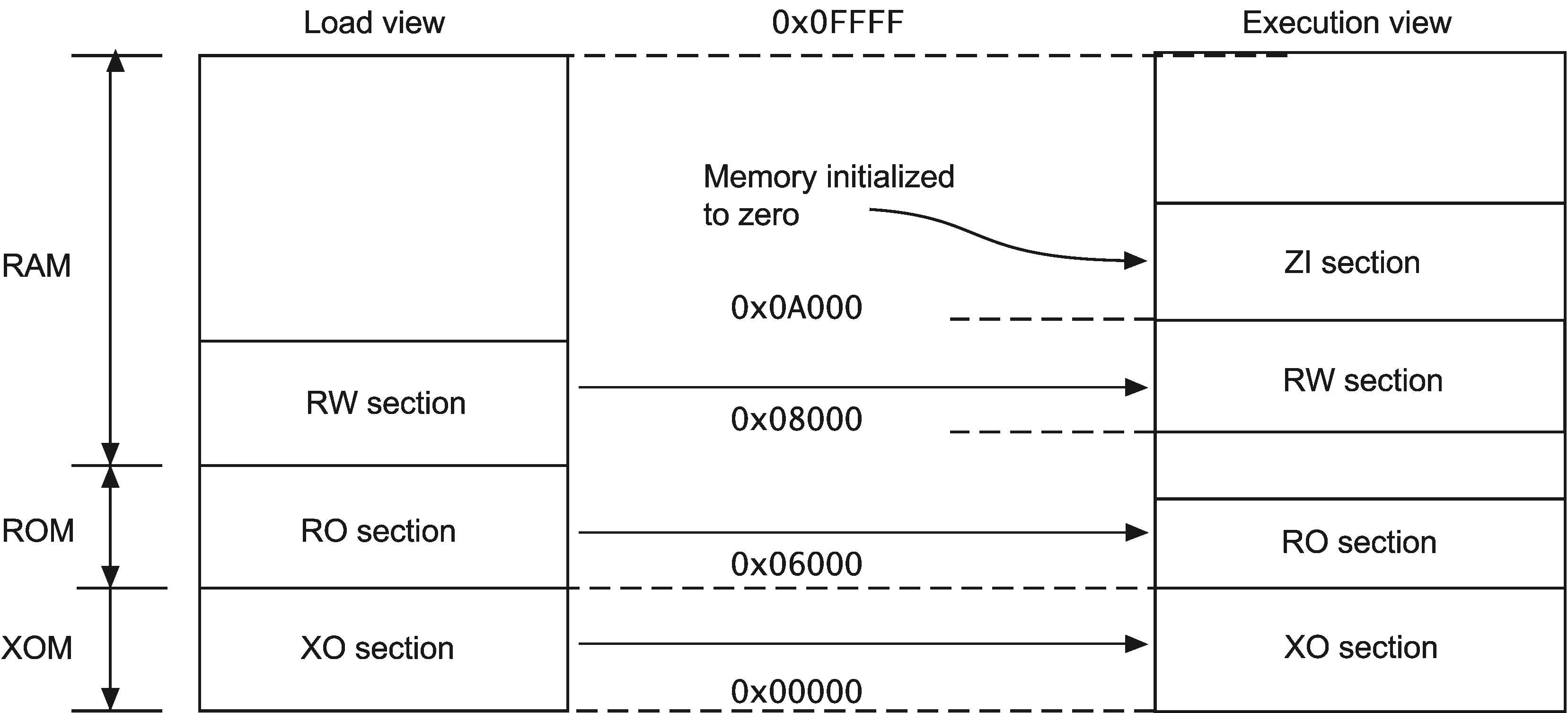
Table 3-1 Comparing load and execution views
| Load | Description | Execution | Description |
|---|---|---|---|
| Load address | The address where a section or region is loaded into memory before the image containing it starts executing. The load address of a section or a non-root region can differ from its execution address | Execution address | The address where a section or region is located while the image containing it is being executed |
| Load region | A load region describes the layout of a contiguous chunk of memory in load address space. | Execution region | An execution region describes the layout of a contiguous chunk of memory in execution address space. |
A Type 1 image consists of a single load region in the load view and three execution regions placed contiguously in the memory map.
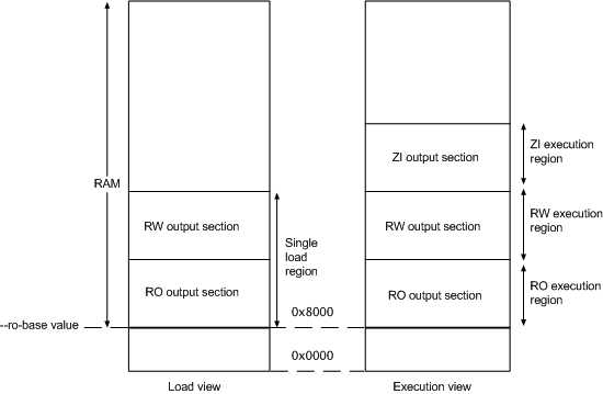
armlink --ro_base 0x8000
Note
0x8000 is the default address, so you do not have to specify --ro_base for the example.Load view
Execution view
--ro_base address to specify the load and execution address of the region containing the RO output. The default address is 0x8000.--zi_base command-line option to specify the base address of a ZI execution region.Load view for images containing execute-only regions
--ro_base. The RO and RW output sections are placed consecutively and immediately after the XO section.Execution view for images containing execute-only regions
--ro_base. The RO, RW, and ZI execution regions are placed contiguously and immediately after the XO execution region.A Type 2 image consists of a single load region, and three execution regions in execution view. The RW execution region is not contiguous with the RO execution region.
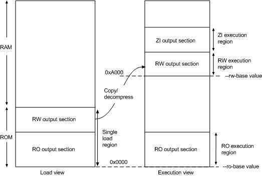
armlink --ro_base 0x0 --rw_base 0xA000
--ro_base address to specify the load and execution address for the RO output section, and --rw_base address to specify the execution address of the RW output section. If you do not use the --ro_base option to specify the address, the default value of 0x8000 is used by armlink. For an embedded system, 0x0 is typical for the --ro_base value. If you do not use the --rw_base option to specify the address, the default is to place RW directly above RO (as in a Type 1 image).--zi_base command-line option to specify the base address of a ZI execution region.--ro_base. The RO and RW output sections are placed consecutively and immediately after the XO section.--ro_base. The RO execution region is placed contiguously and immediately after the XO execution region.--xo_base address, then the XO execution region is placed in a separate load region at the specified address.A Type 3 image is similar to a Type 2 image except that the single load region is split into multiple root load regions.
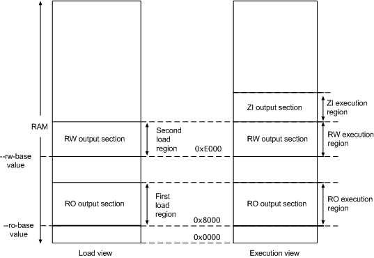
armlink --split --ro_base 0x8000 --rw_base 0xE000
--ro_base addressaddress, for example, the address of the first location in ROM. If you do not use the --ro_base option to specify the address, the default value of 0x8000 is used by armlink.--rw_base addressaddress. If this option is used with --split, this specifies both the load and execution addresses of the RW region, for example, a root region.--split--ro_base and --rw_base.--ro_base. The RO and RW output sections are placed consecutively and immediately after the XO section.--split, then the one load region contains the XO and RO output sections, and the other contains the RW output section.--ro_base. The RO execution region is placed contiguously and immediately after the XO execution region.--split, then the XO and RO execution regions are placed in the first load region, and the RW and ZI execution regions are placed in the second load region.--xo_base address, then the XO execution region is placed at the specified address in a separate load region from the RO execution region.The linker places input sections in a specific order by default.
FIRST or LAST execution region attribute.--tiebreaker=cmdline option uses a more predictable order based on the order the section appears on the command line.--sort=algorithm command-line option. The linker might change the algorithm to minimize the amount of veneers generated if no algorithm is chosen..ANY module selectors with optional input section selectors.LoadRegion 0x8000 { ExecRegion1 0x0000 0x4000 { *(sections) *(moresections) } ExecRegion2 0x4000 0x2000 { *(evenmoresections) } }
You can make sure that a section is placed either first or last in its execution region. For example, you might want to make sure the section containing the vector table is placed first in the image.
--first and --last linker command-line options to place input sections.FIRST and LAST in the scatter file to mark the first and last input sections in an execution region if the placement order is important.FIRST and LAST must not violate the basic attribute sorting order. For example, FIRST RW is placed after any read-only code or read-only data.
3.1 The structure of an ARM ELF image
标签:which processes cond deb rar protect within out 包含
原文地址:https://www.cnblogs.com/qiyuexin/p/9024695.html